Z80ALL, a standalone Z80 computer

Bill Shen
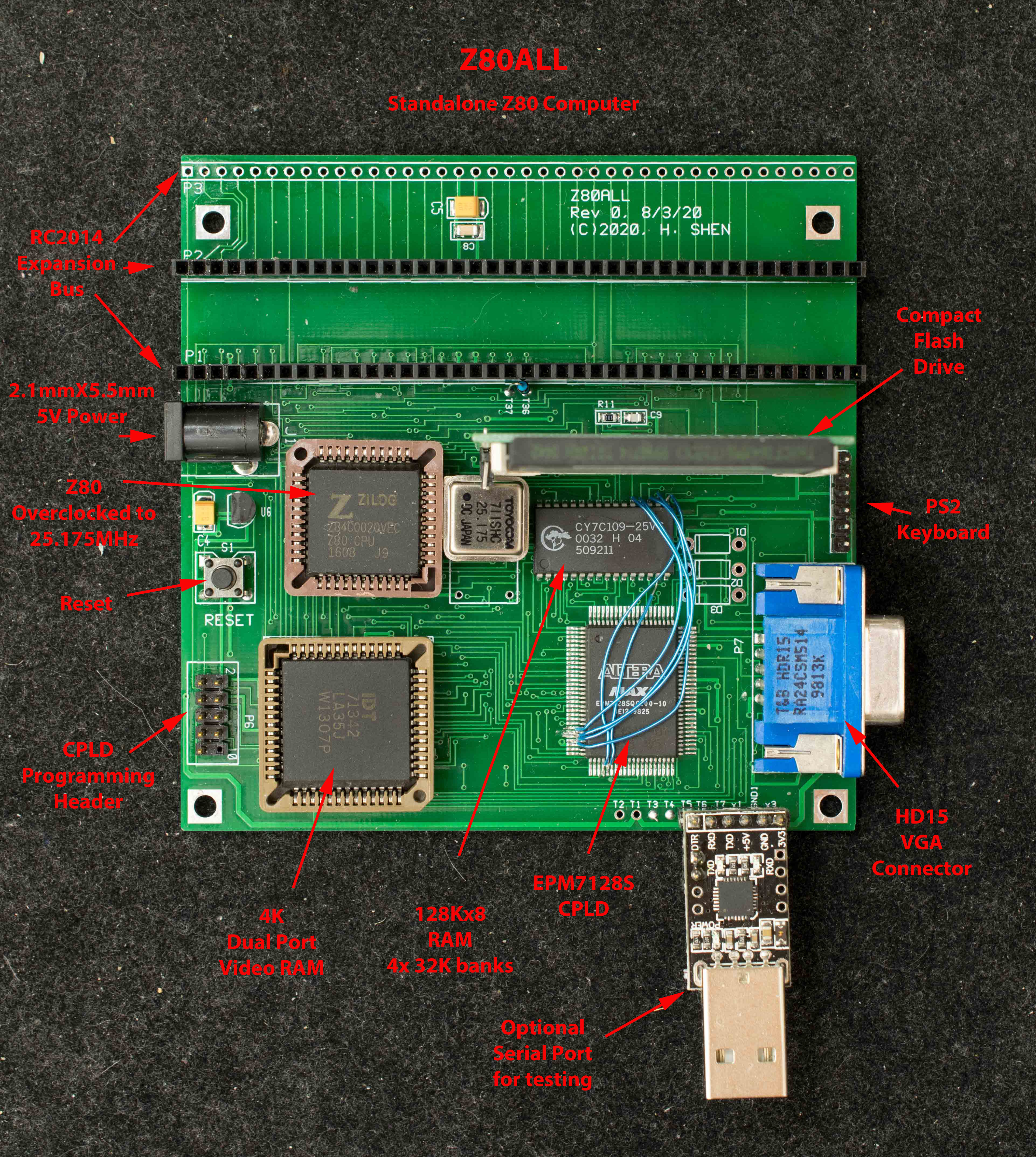
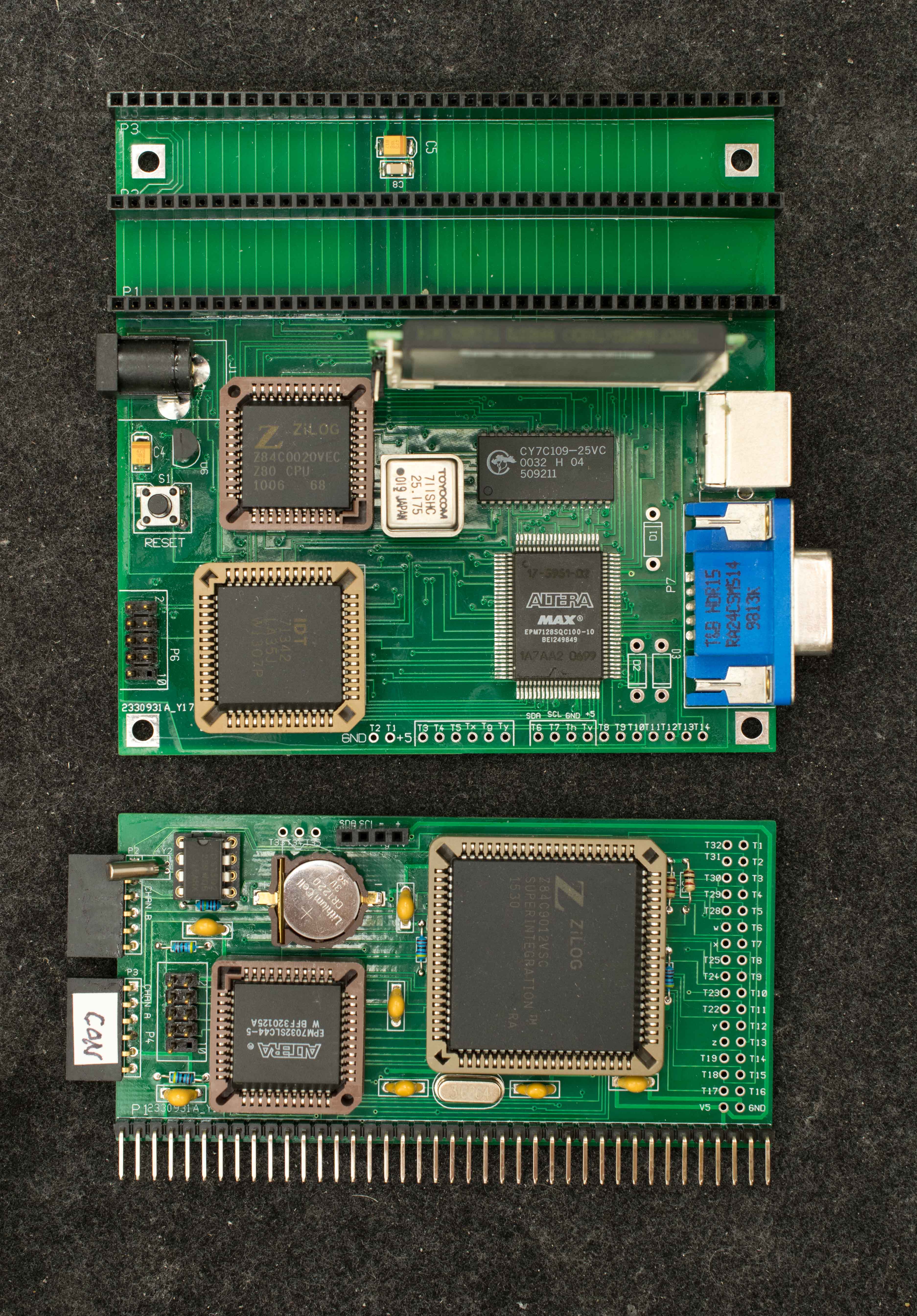
Z80ALL is my first attempt to build a standalone CP/M system. It is the combination of two previous designs, ZRCC and VGARC. The goal is an economical Z80 SBC with VGA and PS2 keyboard on a 4"x4" 2-layer pc board. This is the features of Z80ALL
- Z80 overclocked to 25.175MHz
- 128K RAM in 4 32-K banks
- 4K dual port video RAM with user programmable font table.
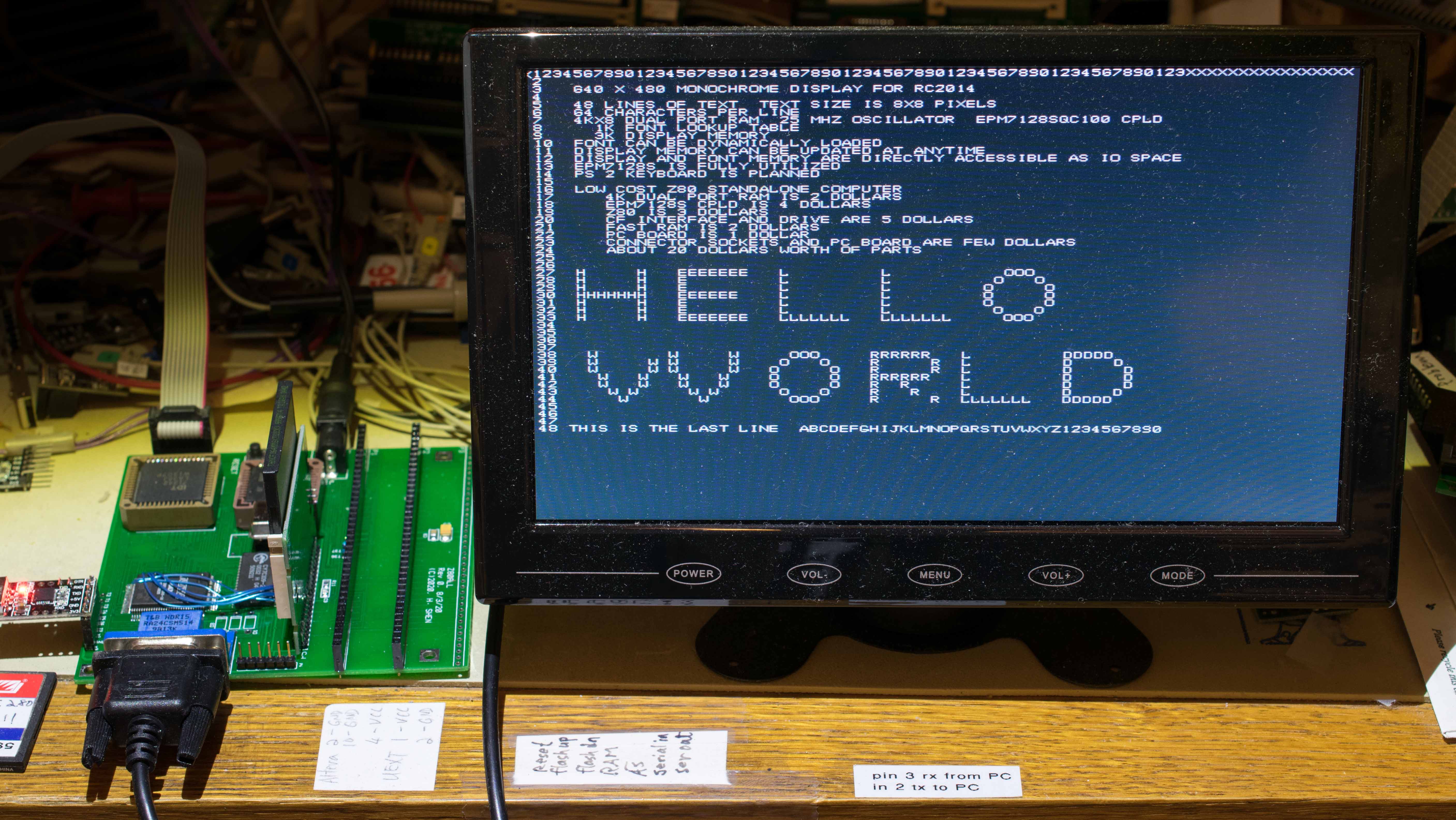
- VGA monochrome interface, 64 columns X 48 rows
- EPM7128S CPLD with the following features
- - Small ROM to bootstrap from CF disk
- - VGA timing circuit
- - Serial port for hardware/software development
- - Memory bank select logic
- - Decoding logic for compact flash
- IDE44 interface for compact flash drive
- CP/M ready
- PS2 keyboard interface
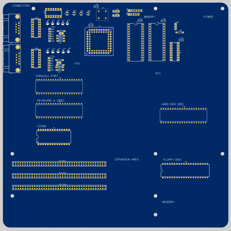
- 3 RC2014 expansion bus
- Optional USB-serial connector
- 102mm X 102mm 2-layer pc board
- Nominal power consumption of 5V 300mA
Z80ALL boots through the 32-byte ROM embedded in the CPLD which loads and executes code on compact flash's Master Boot Block; which, in turn, loads and executes a monitor located in Track 0 of compact flash; thus the CF disk serves as the traditional EPROM loading code into RAM and executing in RAM.
Software development is through the optional serial port in CPLD. This is how test software is loaded and ran. The serial port function can be removed later to free up more CPLD resources for other functions.
The VGA interface is through a 4Kx8 dual port RAM. One side of the dual port RAM is read/write accessible by Z80 as 4K I/O space. 3K of the I/O space maps to each character of the 64x48 display; the top 1K is font lookup table for characters 0x0-0x7F. Z80 can read/write to its side of dual port RAM anytime without affecting video display quality. The other side of the dual port RAM is read only accessible by VGA timing circuit in CPLD. It reads each character and looks up corresponding font and output the pixel representation of the character on RGB output. This is a monochrome display although it is possible to display color characters as suggested by Alan Cox in previous discussion.
PS2 keyboard interface is simple software bit-bang registers. Currently the PS2 function is not implemented due to limited CPLD hardware resources.
New revision of Z80ALL will correct the current engineering changes and implement the PS2 keyboard function. The goal is a Z80 computer with its own keyboard and monitor running CP/M.
Homepage for Z80ALL is currently under construction here:
https://www.retrobrewcomputers.org/doku.php?id=builderpages:plasmo:z80all
Bill

Nick Brok
Bill Shen
I did even know I have a retro-wiki account until now. Is it in retrobrewcomputer.org? I'll go look around. Google groups just changed its format, but in the old format you have a pull down option in when replying so you can send me private email instead. This option may not be available in Google's new format.
Bill
Nick Brok

Jacob Hahn
Bill Shen
Jacob,
Just about all my boards were autorouted. It took too much time to manually route and I don't see any advantage electrically.
I have not done PS2, so I can't really explain how it works. My starting point is what Alan Cox had said about holding PS2 keyboard from transmitting by disabling the clock line. When software is ready to receive character, enable the clock and listen for incoming characters.
----------
The PS/2 keyboard buffers 16 keypresses or so.
The trick used by Lee and copied by everyone else is that the PC can pull the clock line down to say 'I want to be sender' and just leave it that way until it next wants to poll. At that point you let it float back high and wait for 250µs or so to see if the keyboard starts sending you stuff. You then either poll it every timer tick (Fuzix does ever 1/50th sec or so) and empty the buffer, or for a CP/M like OS you can just do the poll in the BIOS calls.
So the sequence looks something like
let clock float
wait a bit for keyboard to respond
if it responds collect bytes
set clock low (PC wants to send)
return
If you pull the clock low mid character from the keyboard then it will resend it as well next time it can - I had some very strange behaviour initially because my driver didn't always listen for the last stop bit before lowering the clock !
---------

Colin MacArthur
Bill Shen
Bill

Frank P.
Jacob Hahn
Thanks.

Karl Albert Brokstad
Bill Shen
Your design is impressive. It should make a full-feature Z80 computer with plenty of memory and expansion.
My motivation with Z80ALL is designing with few inexpensive parts that I can iterate numerous times quickly & cheaply with different board format and different CPU. Parts & board cost are about $20 and since I can reuse the socketed parts, it is about $10 to iterate a design. Z180 is attractive because it can run at 36MHz which is SVGA (800x600) pixel clock frequency. I'm mostly interested in exploring video capabilities right now.
Bill
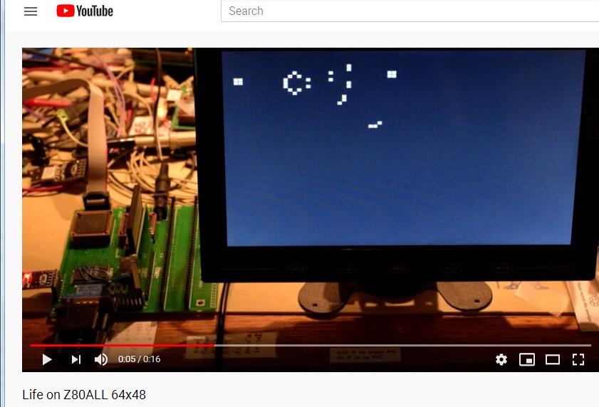
Bill Shen
This is a video of Conway's Game of Life running on Z80ALL. The software itself is only 500 bytes, it takes advantage of the read/write capability of the video memory and perform required calculations directly on the video memory. The dual port memory impose no restriction on Z80's access and the display quality is not at all affected by the numerous Z80 read/write access.
https://youtu.be/qt8Mx9dZJj0
Bill
Bill Shen
It turns out INDR and OTDR instructions have a difference that I didn't expect (the difference is clearly documented, had I bother to read the documentation). For INDR, reg B content is placed on A15-A8 for the I/O read operation and THEN decremented. For OTDR, reg B is decremented FIRST and the decremented value placed on A15-A8 for the I/O write operation. Oh boy, that had me going in circle for few days, until I remembered that "When All Else Fails, Read The Instructions".
This is scrolling algorithm that took me a week to figure out:
ld c,line1_4 ;C points to top line
mov4ln:
;move lines 2,3,4 to lines 1,2,3
ld hl,buf+191 ;HL points to buffer
ld b,255 ;read line 2,3,4 starting with end of line 4
ld a,192
save3ln:
ind
dec a
jp nz,save3ln
;move line 5 to line 4
inc c ;line 5 is next block, b=0-63
ld hl,buf+255
ld b,63
indr
in a,(c) ;do the last byte with b=0
ld (hl),a
;buf now contains line 2,3,4,5; write it to first block
dec c
ld hl,buf+255
ld b,0
otdr
;
;do this 11 more times to scroll the entire screen.
With 25MHz Z80, it takes about 6 milliseconds to scroll the screen.
Bill Shen
https://youtu.be/5jmb6yp2W84
Bill
Bill Shen
This is a standalone Z80all with the quad serial board as the console. CP/M BIOS is modified so it can accept input either through PS2 keyboard or serial console and send output to both VGA monitor and the serial console. Software is developed on Windows workstation and updated software can be loaded via serial port at 115200. While in CP/M environment, file transfer is accomplished using XMODEM through the console serial port.
It is possible to operate Z80all standalone without quad serial board, but then the only way to communicate with outside is by moving CF disk between Z80all and the workstation.
Design files for standalone Z80all are documented here. Please note that software and CPLD firmware are changing fairly quickly right now.
Bill
Bill Shen
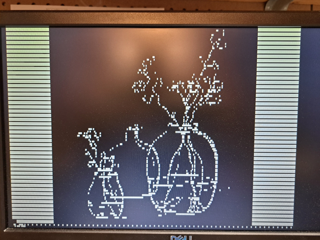
Slowly a solution emerged; I have found full-length animated GIF of Bad Apple and tool on ezgif.com to reduce resolution and split into multiple frames. Then there is the "image2cpp" tool that converts multiple image frames to format suitable for 128x64 OLED display. So I down convert the BadApple GIF file to 85x64 resolution (Bad Apple was in 4:3 ratio) and split the first 40% of the video into 1000 frames. Use image2CPP to convert each frame to 128x64 OLED format binary data so 1000 frames is 1 meg of binary data. The data is XMODEM to known location on the CF disk as a contiguous file (specifically the first file of a freshly formatted drive D) so the application knows where to find the data file.
Currently it took 53 seconds to play 1000 frames, so it is slightly slower than the 20 frames/sec GIF player. I should be able to optimize the I2C routine to reach 20 frames/sec. Attached is animated GIF of the first 18 seconds of BadApple. There are lots of artifacts due to optimization and compression; the video looks much better in real life.
Now I need a sound card.
Bill
Bill Shen
YouTube video of first 50 seconds is here. https://youtu.be/KYVQk8Nyg84
Only fonts in the range of 0x0-0xF are changed so the remaining fonts are still usable such as overlaying text over the image. An example is the diagnostic information at upper left of the monitor.

Michael Earls (cerkit)
Bill Shen
Lately I have been thinking about how to "race the beam" with 25MHz Z80 so I can output "BadApple" video in full VGA resolution. The BadApple image files are stored in the CF disk so Z80 needs to access it and paints the VGA screen at 1 pixel every 40nS. Z80 can execute the "pop" stack instruction in 10 clocks which fetches two bytes of data. I can load these two bytes into a shift register and shift the pixel data out at 25MHz rate. I can fill with a Z80 instruction that takes 6 clock cycle to execute (e.g., INC bc) so Z80 reads two bytes every 16 clock cycles. Repeat that 40 times to paint a 640 pixel horizontal line. Do this for 480 lines for a full VGA screen, then during the vertical retrace it'll have small amount of time to fetch next image from CF disk and repeat. I've done that with 25MHz 65C02 but the image is static. Video with decent frame rate is significantly more difficult.
Bill
Bill Shen
While Z80all has three 40-pin RC2014-compatible expansion slots, the 25.175MHz system clock render them unusable for most existing RC2014 boards. At the same time, it is already a standalone computer with banked 128K RAM, CF interface, video, keyboard and even I2C, so there are only few RC2014 functions it needs such as sound, network, discrete I/O, and most importantly, serial ports. Serial port is particularly important because it is the link to my workstation for software transfer via Intel Hex upload or XMODEM in CP/M. It is possible to transfer files via CF disk, but serial transfer is the quickest and easiest.
I only have two serial boards that'll work with 25.175MHz clock; Quad Serial with OX16C954, and KIORC with Z84C90. So lately I'm working on a monitor that will auto detect the presence of Quad Serial or KIORC or no serial board at all. As long as the monitor has ability to auto detect serial hardware and transfer files, the CP/M BIOS does not need such reconfigurability because I can always transfer and install CP/M with BIOS configured for a particular serial hardware. Z80all will also work as a standalone computer without any serial port. It is a 4-chip 25MHz CP/M computer that's really quite responsive.
Picture shows Z80all with KIORC serial board installed and a Quad serial board lying in the foreground. The memory dump displayed on the VGA monitor is also displayed over serial port on TeraTerm terminal.
Bill

ladislau szilagyi
Bill Shen
I'm an admirer of you works on HiTech C which has spurred me to continue working on a standalone, self-hosting Z80 computer, so I'm delighted you are interested in Z80all. However, it is currently an experimental hardware and I'm reluctant to sell it, but if you'll pay for shipping to Romania from USA (about $30), I'm happy to ship you an assembled/tested Z80all + KIORC. In reality, Z80all and KIORC are both simple with few parts so shipping across the world is the most expensive part. Please PM me with your address.
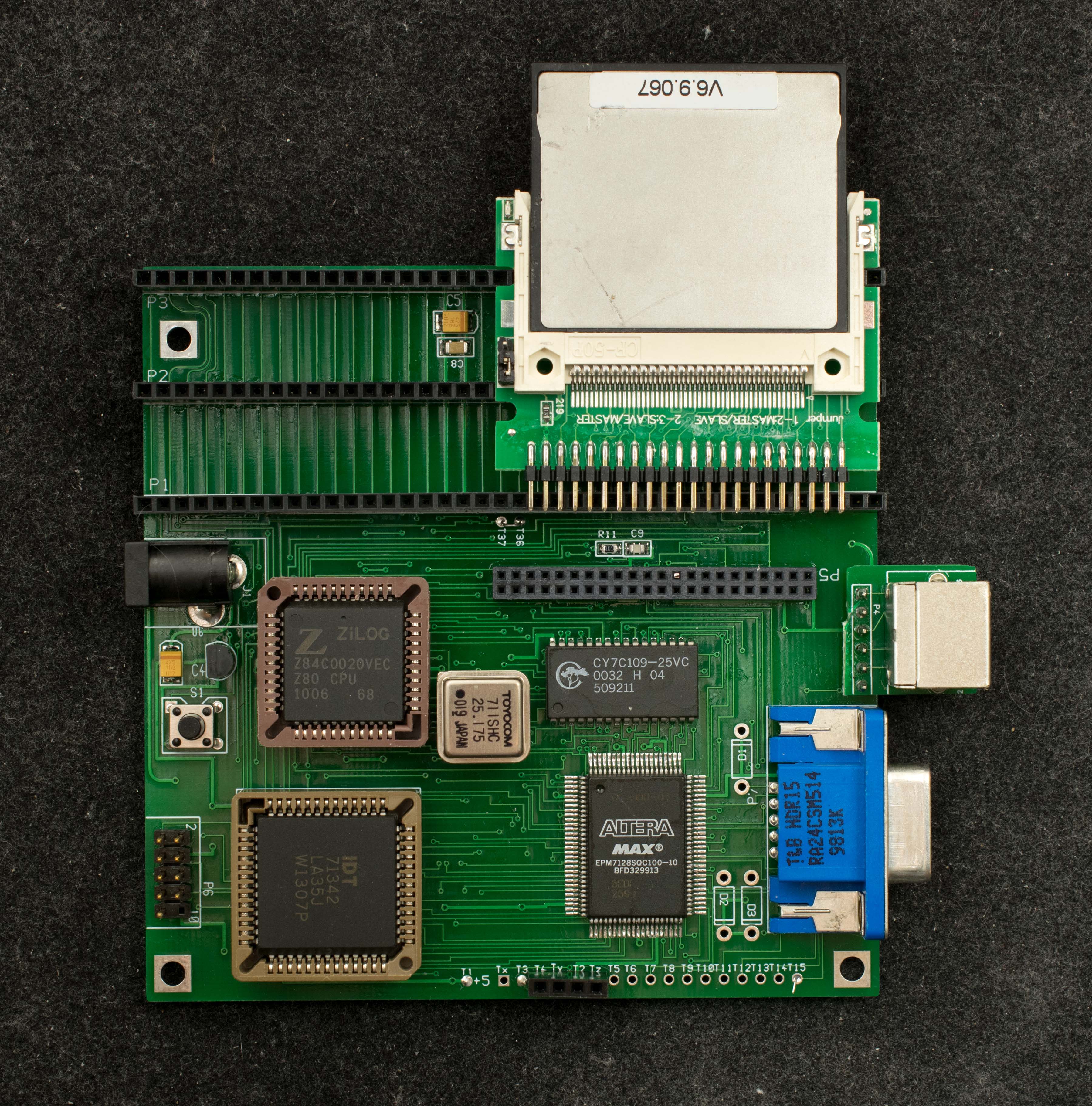
In fact, I have one bare pc board remaining so I put together a new Z80all this morning without all the experimental cuts and jumpers of earlier boards. Attached are pictures, front and back of the newly assembled Z80all. I added a connector for CF adapter so it is easy to disassemble and ship. The 2 short jumpers at the back are for I2C modification and the long jumper is 60Hz interrupt generated by VGA's vertical sync. The software I mentioned last night is very new, so I'll need a few days to test it with the new hardware. All the software (except the small bootstrap in CPLD) are contained in the CF disk, so it is easy to make software changes.
Z80 and KIO can be overclocked to 29.5MHz so they are very stable at 25MHz. I'm not worry about VGA interface, but I'm somewhat concerned about PS2 timings. I've only tested it with Dell keyboard salvaged from my old computers. The CF interface should be quite robust, I expect it to work with most brands of CF disk. This version of Z80all requires a CF disk pre-loaded with system software, so I've published a CF image containing the required software which I transfer to a new CF disk use Windows Win32DiskImager. Once system software is installed, software updates can be done using serial port (XMODEM and Intel hex upload).
There is also some discussion of Z80all on retrobrewcomputers.org. Z80all home page will be updated with KIORC in next few days.
Delighted that you are interesed in Z80all.
Bill
Bill Shen
Z80all discussion on retrobrewcomputers: https://www.retrobrewcomputers.org/forum/index.php?t=msg&th=512&start=0&
Z80all homepage: https://www.retrobrewcomputers.org/doku.php?id=builderpages:plasmo:z80all:z80all_rev1:z80allr1quad
Bill Shen
I'll update the homepages, build up all 5 boards to make sure they all work, sent one off to Ladislau to test and auction off the rest.
Bill
ladislau szilagyi
Bill Shen
Thank you for believing in Z80ALL and have developed so many software for it. I'm juggling several projects but managed to build up five boards of the latest revision and they all passed memory test, zexall test, xmodem transfer, and files copy with verify, so I'm satisfied that the updated design is solid. I'll send a board your way next week so you can do more testing. It should behave exactly the same as the bodged board you currently have.
Bill
ladislau szilagyi

Stefan V. Pantazi
Bill Shen
I'm glad to hear you are building up a Z80ALL. I'm providing a check list below to make sure we are on the same page:
1. You should have a pc board with silk screen at the solder side that says "Z80ALL Rev2 9/13/23 H. SHEN"
2. Check your CF adapter to make sure there is a small jumper installed to indicate master CF disk. When the CF disk is inserted in the adapter, the CF disk label should face the CPLD.
3. My board's current consumption is 270mA, but 300mA is OK.
4. You should get the design information from this homepage:5. You do not need KIORC to boot up. but you do need the correct CF image to boot. The link to CF image is on the homepage.
6. Here is the link again:
https://www.retrobrewcomputers.org/lib/exe/fetch.php?media=builderpages:plasmo:z80all:z80all_rev1:z80all_kq_vga0x0_cpm1_8_monitor091.zip
7. I use Win32DiskImager to copy the CF image to a new CF disk. Z80ALL's CF interface is quite robust, I believe it should work with majority of CF disk brands. Since your disk already work with Simple80 and ZRCC, I believe it should work just fine.
8. When power is applied you should see CF disk blink once which is bootstrapping from the CF disk. CF disk will also blink the same way after reset button is pressed and released. You do not need the VGA or PS2 plug in to see the CF blinking.
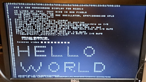
9. VGA screen should show a splash screen with big "HELLO WORLD".
I'll stop here waiting for you to confirm we have the same setup
Bill
Stefan V. Pantazi
Stefan V. Pantazi
Stefan
Bill Shen
32MB CF disk should be fine. You may lose some space on drive D, but that won't affect the ability to bootstrap. The critical files are on the first 128KB of CF disk.
I noticed the CF capacitor at the back says "101K". That doesn't sound like 100pF. Are you sure it is a 100pF capacitor? If you don't have a 100pF capacitor, I rather you remove it. CF operation may not be as reliable, but it may be sufficient to boot up.
Bill

Stefan Pantazi
Bill Shen
Cleaning your board with isopropyl alcohol will help you with visual inspection.
I don't think 10% more current is a problem. My assumption is your CPLD is working. What I think I'll do tomorrow is revisit the earlier, simpler designs that had serial bootstrap capability. So the design can simplify to Z80, RAM, and CPLD talking to a serial port. Then we'll work in the CF and dual port RAM.
The board already has a serial connector--it is the 6-pin T3-T4-T5-Tx-Tg-Ty at the edge of the board. It is designed for direct connection to a 6-pin CP2102 USB-serial adapter.
Bill
Stefan V. Pantazi
Bill Shen
I bought my batch of used EPM7128S cheaply, something like 3 for a dollar, but this was 10+ years ago. You may still find them at good price from eBay once in a long while. I bought a big lot of EPM7064S that way. With EPM7128S and EPM7064S it is no longer necessary to have big stockpile of TTL logic. Better yet, they are re-programmable so I can design a board quickly and figure out how to make it work later.
Attached is modified CPLD with serial port at 115200. When boot up, it will put out 987650321 to indicate it is alive. If you sent a 256-byte binary serial data before the 987650321 sequence completed, it will save the data in RAM and execute it. You should remove dual port RAM and CF disk to simplify your circuit. It draws 190mA on my setup. If you see 987650321 sequence, it means your Z80+CPLD is working. I'll supply a 256-byte program in a while which should check out Z80+RAM+CPLD.
Bill
Stefan V. Pantazi
Bill Shen
Next we'll load a 256-byte Intel Hex loader, zrserld.bin, then follow with monitor, zrcmon.hex
During the count-down of 987650321, send zrserld.bin as binary file. <- Important to specify it as binary file.
It will respond with
ZRC Loader v0.0
Auto start at 0xB400
Then you can leisurely send zrcmon.hex but don't check the binary box. You should see
ZRC Monitor v0.9 2/11/21
ZRCmon has a 't' command to test memory, you should see OK0 OK1 OK2 but then hang. This is because ZRC has much bigger memory than Z80ALL.
Bill
Bill Shen
If you've passed memory diagnostic of RAM, then you can install CF disk and use the 'r' command to read contents of CF disk.
Bill
Stefan V. Pantazi
Bill Shen
+0000 : 3E E0 D3 16 3E 01 D3 11 3E EF D3 17 DB 17 E6 80 >...>...>.......
+0010 : C2 0C B0 AF D3 15 D3 14 16 F8 21 00 B4 0E 10 3E ..........!....>
+0020 : 01 D3 12 7A FE 00 CA 00 B4 D3 13 3E 20 D3 17 DB ...z.......> ...
+0030 : 17 E6 08 CA 2F B0 06 00 ED B2 ED B2 14 C3 1F B0 ..../...........
+0040 : 94 B0 C3 00 B4 80 47 CD 6B B0 77 80 47 23 15 20 ......G.k.w.G#.
+0050 : F6 CD 6B B0 ED 44 B8 20 07 3E 2E CD 94 B0 18 AD ..k..D. .>......
+0060 : 3E 3F 18 F7 3E 55 CD 94 B0 18 A2 D5 CD C8 B0 CD >?..>U..........
+0070 : 80 B0 07 07 07 07 57 CD C8 B0 CD 80 B0 B2 D1 C9 ......W.........
+0080 : D6 30 FE 0A F8 E6 5F D6 07 C9 7E FE 00 C8 CD 94 .0...._...~.....
+0090 : B0 23 18 F6 C5 4F 06 08 CD AF B0 79 0F 38 08 CD .#...O.....y.8..
+00A0 : AF B0 10 F8 C1 18 14 CD BB B0 10 F0 C1 18 0C F5 ................
+00B0 : AF D3 F9 3E 09 3D C2 B5 B0 F1 C9 F5 F6 FF D3 F9 ...>.=..........
+00C0 : 3E 09 3D C2 C2 B0 F1 C9 DB F8 E6 01 28 FA DB F9 >.=.........(...
+00D0 : C9 0A 0D 5A 41 4C 4C 20 4C 6F 61 64 65 72 20 76 ...ZALL Loader v
+00E0 : 30 2E 30 0A 0D 41 75 74 6F 20 73 74 61 72 74 20 0.0..Auto start
+00F0 : 61 74 20 30 78 42 34 30 30 0A 0D 00 00 00 00 00 at 0xB400.......
+0100 : 00 00 00 00 00 00 00 00 00 00 00 00 00 00 00 00 ................
+0110 : 00 00 00 00 00 00 00 00 00 00 00 00 00 00 00 00 ................
+0120 : 00 00 00 00 00 00 00 00 00 00 00 00 00 00 00 00 ................
+0130 : 00 00 00 00 00 00 00 00 00 00 00 00 00 00 00 00 ................
+0140 : 00 00 00 00 00 00 00 00 00 00 00 00 00 00 00 00 ................
+0150 : 00 00 00 00 00 00 00 00 00 00 00 00 00 00 00 00 ................
+0160 : 00 00 00 00 00 00 00 00 00 00 00 00 00 00 00 00 ................
+0170 : 00 00 00 00 00 00 00 00 00 00 00 00 00 00 00 00 ................
+0180 : 00 00 00 00 00 00 00 00 00 00 00 00 00 00 00 00 ................
+0190 : 00 00 00 00 00 00 00 00 00 00 00 00 00 00 00 00 ................
+01A0 : 00 00 00 00 00 00 00 00 00 00 00 00 00 00 00 00 ................
+01B0 : 00 00 00 00 00 00 00 00 00 00 00 00 00 00 00 00 ................
+01C0 : 00 00 00 00 00 00 00 00 00 00 00 00 00 00 00 00 ................
+01D0 : 00 00 00 00 00 00 00 00 00 00 00 00 00 00 00 00 ................
+01E0 : 00 00 00 00 00 00 00 00 00 00 00 00 00 00 00 00 ................
+01F0 : 00 00 00 00 00 00 00 00 00 00 00 00 00 00 00 00 ................
Above is track 00 sect 00 of my Z80ALL. Data doubling is strange.
Do a read of track 00 sector f0. This is where splash screen is stored. Also read 00-fd. The CF bootstrap process is loading the program in 00-00, which will load data and program from 00 f0 to 00-ff
Below is data from my CF disk
>read CF disk track:0x00 sector:0xf0
+0000 : 31 32 33 34 35 36 37 38 39 30 31 32 33 34 35 36 1234567890123456
+0010 : 37 38 39 30 31 32 33 34 35 36 37 38 39 30 31 32 7890123456789012
+0020 : 33 34 35 36 37 38 39 30 31 32 33 34 35 36 37 38 3456789012345678
+0030 : 39 30 31 32 33 34 35 36 37 38 39 30 31 32 33 34 9012345678901234
+0040 : 32 00 00 00 00 00 00 00 00 00 00 00 00 00 00 00 2...............
+0050 : 00 00 00 00 00 00 00 00 00 00 00 00 00 00 00 00 ................
+0060 : 00 00 00 00 00 00 00 00 00 00 00 00 00 00 00 00 ................
+0070 : 00 00 00 00 00 00 00 00 00 00 00 00 00 00 00 00 ................
+0080 : 33 20 20 20 36 34 30 20 58 20 34 38 30 20 4D 4F 3 640 X 480 MO
+0090 : 4E 4F 43 48 52 4F 4D 45 20 44 49 53 50 4C 41 59 NOCHROME DISPLAY
+00A0 : 20 46 4F 52 20 52 43 32 30 31 34 00 00 00 00 00 FOR RC2014.....
+00B0 : 00 00 00 00 00 00 00 00 00 00 00 00 00 00 00 00 ................
+00C0 : 34 00 00 00 00 00 00 00 00 00 00 00 00 00 00 00 4...............
+00D0 : 00 00 00 00 00 00 00 00 00 00 00 00 00 00 00 00 ................
+00E0 : 00 00 00 00 00 00 00 00 00 00 00 00 00 00 00 00 ................
+00F0 : 00 00 00 00 00 00 00 00 00 00 00 00 00 00 00 00 ................
+0100 : 35 20 20 20 34 38 20 4C 49 4E 45 53 20 4F 46 20 5 48 LINES OF
+0110 : 54 45 58 54 20 20 54 45 58 54 20 53 49 5A 45 20 TEXT TEXT SIZE
+0120 : 49 53 20 38 58 38 20 50 49 58 45 4C 53 00 00 00 IS 8X8 PIXELS...
+0130 : 00 00 00 00 00 00 00 00 00 00 00 00 00 00 00 00 ................
+0140 : 36 20 20 20 36 34 20 43 68 61 72 61 63 74 65 72 6 64 Character
+0150 : 73 20 70 65 72 20 6C 69 6E 65 00 00 00 00 00 00 s per line......
+0160 : 00 00 00 00 00 00 00 00 00 00 00 00 00 00 00 00 ................
+0170 : 00 00 00 00 00 00 00 00 00 00 00 00 00 00 00 00 ................
+0180 : 37 20 20 20 34 4B 58 38 20 44 55 41 4C 20 50 4F 7 4KX8 DUAL PO
+0190 : 52 54 20 52 41 4D 2C 20 32 35 20 4D 48 5A 20 4F RT RAM, 25 MHZ O
+01A0 : 53 43 49 4C 4C 41 54 4F 52 2C 20 45 50 4D 37 31 SCILLATOR, EPM71
+01B0 : 32 38 53 51 43 31 30 30 20 43 50 4C 44 00 00 00 28SQC100 CPLD...
+01C0 : 38 20 20 20 20 20 31 4B 20 46 6F 6E 74 20 6C 6F 8 1K Font lo
+01D0 : 6F 6B 75 70 20 74 61 62 6C 65 00 00 00 00 00 00 okup table......
+01E0 : 00 00 00 00 00 00 00 00 00 00 00 00 00 00 00 00 ................
+01F0 : 00 00 00 00 00 00 00 00 00 00 00 00 00 00 00 00 ................
track:0x00 sector:0xFD
+0000 : 21 00 C3 3A 19 B4 B5 6F 7E FE E1 20 07 AF 32 15 !..:...o~.. ..2.
+0010 : B4 C3 1C BE FE E2 20 04 AF 32 16 B4 E1 C3 C2 BD ...... ..2......
+0020 : 3A 19 B4 FE F0 20 07 3E 01 32 14 B4 18 94 E5 3A :.... .>.2.....:
+0030 : 15 B4 FE 00 21 00 C3 28 03 21 80 C3 3A 19 B4 B5 ....!..(.!..:...
+0040 : 6F 7E FE E1 20 08 3E 01 32 15 B4 C3 66 BE FE E2 o~.. .>.2...f...
+0050 : 20 08 3E 01 32 16 B4 C3 66 BE FE E4 20 0C 3A 17 .>.2...f... .:.
+0060 : B4 EE 01 32 17 B4 E1 C3 C2 BD 67 3A 16 B4 B7 7C ...2......g:...|
+0070 : 28 02 E6 1F 67 3A 17 B4 FE 00 7C 28 12 FE 7B 30 (...g:....|(..{0
+0080 : 0E FE 61 30 08 FE 5B 30 06 FE 41 38 02 EE 20 26 ..a0..[0..A8.. &
+0090 : 00 24 E1 C9 C5 F5 3A 1A B4 1F 30 0C DB 89 CB 57 .$....:...0....W
+00A0 : 28 FA F1 F5 D3 88 18 10 3A 1B B4 1F 30 0A DB C5 (.......:...0...
+00B0 : E6 40 28 FA F1 F5 D3 C0 F1 F5 ED 4B 11 B4 FE 08 .@(........K....
+00C0 : 20 08 3E 20 ED 79 05 C3 17 BF FE 0D 20 0C 3A 13 .> .y...... .:.
+00D0 : B4 ED 79 3E C0 A0 47 C3 17 BF FE 0A 20 22 3A 13 ..y>..G..... ":.
+00E0 : B4 ED 79 3E 40 80 47 30 2E 3E 0B B9 20 28 CD 27 ..y>@.G0.>.. (.'
+00F0 : BF 01 0B C0 AF ED 79 04 20 FB 01 0B C0 C3 17 BF ......y. .......
+0100 : ED 79 78 FE 3F 28 1D FE 7F 28 19 FE BF 28 15 FE .yx.?(...(...(..
+0110 : FF 28 11 04 18 01 0C ED 78 32 13 B4 3E 5F ED 79 .(......x2..>_.y
+0120 : ED 43 11 B4 F1 C1 C9 E5 D5 0E 00 21 BF C4 06 FF .C.........!....
+0130 : 3E C0 ED AA 3D C2 32 BF 0C 21 FF C4 06 3F ED BA >...=.2..!...?..
+0140 : ED 78 77 0D 21 FF C4 06 00 ED BB 0C 3E 0C B9 C2 .xw.!.......>...
+0150 : 2B BF D1 E1 C9 5A 41 4C 4C 51 20 4D 6F 6E 69 74 +....ZALLQ Monit
+0160 : 6F 72 20 76 30 2E 39 31 20 33 2F 32 38 2F 32 33 or v0.91 3/28/23
+0170 : 0D 0A 00 4B 49 4F 20 00 51 75 61 64 20 53 65 72 ...KIO .Quad Ser
+0180 : 69 61 6C 20 64 65 74 65 63 74 65 64 0D 0A 00 0D ial detected....
+0190 : 0A 0A 3E 00 0D 0A 3F 00 0D 0A 00 20 70 72 65 73 ..>...?.... pres
+01A0 : 73 20 52 65 74 75 72 6E 20 74 6F 20 65 78 65 63 s Return to exec
+01B0 : 75 74 65 20 63 6F 6D 6D 61 6E 64 00 20 64 6F 6E ute command. don
+01C0 : 65 00 0D 0A 63 6F 6D 6D 61 6E 64 20 61 62 6F 72 e...command abor
+01D0 : 74 65 64 00 6F 20 74 6F 20 61 64 64 72 65 73 73 ted.o to address
+01E0 : 3A 20 30 78 00 20 74 72 61 63 6B 3A 30 78 00 20 : 0x. track:0x.
+01F0 : 73 65 63 74 6F 72 3A 30 78 00 65 61 64 20 43 46 sector:0x.ead CF
Stefan V. Pantazi
Bill Shen
There is a disconnect of image file and CPLD file in Z80ALL homepage. I am attaching the CPLD .pof programming file that verified OK on my hardware setup. Please try that with your CF image that has data doubling in track00, sector 00.
Somewhere there is a combination that works, but I'm confused right now.
Bill
Stefan V. Pantazi
I got the nice HW splash screen and all seems to work fine. I am running zexall and other things off the CF card. So, to conclude, the main problem seems to have been the discrepancy between the CPLD design file and the boot sector format on the CF card. I am sure there is an interesting rationale behind it and would love to learn more. In hindsight, it all makes sense now that it was a software problem, the hardware was nearly 100% there (except for some of my shortcomings with SMD soldering that did not seem to matter much). If it worked from first try, I would not have double checked my soldering, not inquiring about failure modes of CPLD, so I already learned from this a whole lot. So thank you for all this and for the help!
Bill Shen
I'm still confused because not having the latest update of CPLD and software were my first thought when you had trouble booting up yesterday. So when I made the check list, I checked each item against my hardware, so I've thought, but apparently I was mistaken. So I still have this unsettled feeling of done something, but actually did not. Anyway, the bottom line is CPLD design file needs to be updated, and yes, the data in master boot record is in the native 16-bit mode because CPLD ROM is too small to implement the set feature to 8-bit mode.
You still need a serial board like KIORC or QuadSer in order to transfer files from PC to Z80ALL. Ladislau Szilagyi has done amazing software developments on Z80ALL. I hope you'll check his GitHub page, https://github.com/Laci1953.
One of the possible enhancement is having a serial port sufficiently functional to transfer file without KIORC or QuadSer, making it a truly standalone computer all by itself. This was done in its sister design, 65ALL, which you may be interested in because it has same components except the CPU is W65C02.
Bill
Stefan V. Pantazi
Bill Shen
Z80 has 64K of extended I/O space, so it is logical to map 4K of video and fonts to the I/O space. This way every byte is direct accessible I/O so manipulation of screen characters are fast, simple and intuitive. You've probably noticed VT52 cursor movements are easy to implement in Z80ALL. 6502 has no I/O space, so video and fonts implemented for 6502 like VGAxRAM consumes processor memory space.
Bill
Stefan V. Pantazi
Bill Shen
I tend to do exploratory designs in 100-pin QFP CPLD because it has high I/O pinout and I've an abundance of these parts, but you are correct about they being difficult to test before soldering to pc board. My collection of EPM7128SQC are all unlocked, so I have no opportunity to check out unlocking with 12V. I do believe it is like any other EPM7xxxS where JTAG can be unlocked with 12V, HOWEVER, the part may also have the security fuse locked which requires a different process to unlock. I've read about "100mS reset pulse" to clear the security fuse, but I don't know how to do that. I still have a bin with dozens of EPM7xxxS that had the security fuse locked.
Recently GlennSmith has written a procedure about programming ATF150x with Openocd; within it is a passage about unlocking with .svf file. I want to try that when I have a bit of time. You may be interested in that as well.
http://forum.6502.org/viewtopic.php?f=10&t=7920
At the prompt of a forum member, I've started a redesign of Z80ALL with 84PLCC EMP7128S. It all fit on paper, but I have not started the pc board layout process. I have several designs I want to get them all fabricated at the same time, probably in couple weeks time.
Bill
Stefan V. Pantazi
Stefan V. Pantazi
Stefan V. Pantazi
Thank you!
Stefan V. Pantazi
Bill Shen
Stefan V. Pantazi
Bill Shen
Stefan V. Pantazi
I don’t understand your comments about driving 3.6864mhz. Yours must be working because you have 115200 baud serial communication which is derived from 3.6864mhz.

Dave White
Bill Shen
Bill Shen
Bill
Stefan V. Pantazi
Bill Shen

Nicolae Muntean
Hello Thank you for your effort and we are waiting for the gerber ... soon
Nicolae Muntean
HELLO, Thanks for pcb with plcc. I have a question about kiorc, namely where do I find the zakserld.hex file for update?
--
You received this message because you are subscribed to the Google Groups "retro-comp" group.
To unsubscribe from this group and stop receiving emails from it, send an email to retro-comp+...@googlegroups.com.
To view this discussion on the web visit https://groups.google.com/d/msgid/retro-comp/228a394d-0be3-46b7-a743-b17a05ff0430n%40googlegroups.com.