Diesel distributor fuel-injection pumps Diesel-engine management Technical Instruction Bosch Ve Pumps Full download: http://manualplace.com/download/bosch-ve-pumps/ This is the cut pages sample. Download all 66 page(s) at: ManualPlace.com
Published by: ©Robert Bosch GmbH, 1999 Postfach 300220, D-70442 Stuttgart. Automotive Equipment Business Sector, Department for Automotive Services, Technical Publications (KH/PDI2).
Editor-in-Chief: Dipl.-Ing. (FH) Horst Bauer.
Editors: Dipl.-Ing. Karl-Heinz Dietsche, Dipl.-Ing. (BA) Jürgen Crepin, Dipl.-Holzw. Folkhart Dinkler, Dipl.-Ing. (FH) Anton Beer.
Author: Dr.-Ing. Helmut Tschöke, assisted by the responsible technical departments of Robert Bosch GmbH.
Presentation: Dipl.-Ing. (FH) Ulrich Adler, Berthold Gauder, Leinfelden-Echterdingen.
Translation: Peter Girling.
Photographs: Audi AG, Ingolstadt and Volkswagen AG, Wolfsburg.
Technical graphics: Bauer & Partner, Stuttgart.
Unless otherwise specified, the above persons are employees of Robert Bosch GmbH, Stuttgart.
Reproduction, copying, or translation of this publication, wholly or in part, only with our previous written permission and with source credit. Illustrations, descriptions, schematic drawings, and other particulars only serve to explain and illustrate the text. They are not to be used as the basis for design, installation, or delivery conditions. We assume no responsibility for agreement of the contents with local laws and regulations.
Robert Bosch GmbH is exempt from liability, and reserves the right to make changes at any time.
Printed in Germany. Imprimé en Allemagne.
4th Edition, April 1999. English translation of the German edition dated: November 1998.
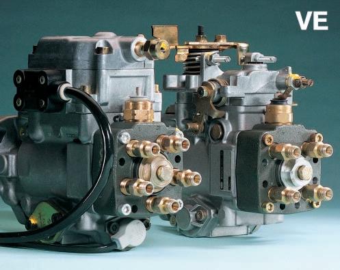
Diesel distributor fuel-injection pumps VE
The reasons behind the diesel-powered vehicle’s continuing success can be reduced to one common denominator: Diesels use considerably less fuel than their gasoline-powered counterparts. And in the meantime the diesel has practically caught up with the gasoline engine when it comes to starting and running refinement. Regarding exhaustgas emissions, the diesel engine is just as good as a gasoline engine with catalytic converter. In some cases, it is even better. The diesel engine’s emissions of CO2, which is responsible for the “green-house effect”, are also lower than for the gasoline engine, although this is a direct result of the diesel engine’s better fuel economy. It was also possible during the past few years to considerably lower the particulate emissions which are typical for the diesel engine. The popularity of the high-speed diesel engine in the passenger car though, would have been impossible without the diesel fuel-injection systems from Bosch. The very high level of precision inherent in the distributor pump means that it is possible to precisely meter extremely small injection quantities to the engine. And thanks to the special governor installed with the VE-pump in passenger-car applications, the engine responds immediately to even the finest change in accelerator-pedal setting. All points which contribute to the sophisticated handling qualities of a modernday automobile. The Electronic Diesel Control (EDC) also plays a decisive role in the overall improvement of the diesel-engined passenger car. The following pages will deal with the design and construction of the VE distributor pump, and how it adapts injected fuel quantity, start-of-injection, and duration of injection to the different engine operating conditions.
Combustion in the diesel engine The diesel engine2
Diesel fuel-injection systems: An overview Fields of application4 Technical requirements4 Injection-pump designs6
Mechanically-controlled (governed) axial-piston distributor fuel-injection pumps VE Fuel-injection systems8 Fuel-injection techniques9 Fuel supply and delivery12 Mechanical engine-speed control (governing)22 Injection timing29 Add-on modules and shutoff devices32 Testing and calibration45 Nozzles and nozzle holders46
Electronically-controlled axialpiston distributor fuel-injection pumps VE-EDC 54
Solenoid-valve-controlled axial-piston distributor fuel-injection pumps VE-MV 60
Start-assist systems 62
Combustion in the diesel engine
Combustion in the diesel engine
The diesel engine
Diesel combustion principle
The diesel engine is a compressionignition (CI) engine which draws in air and compresses it to a very high level. With its overall efficiency figure, the diesel engine rates as the most efficient combustion engine (CE). Large, slow-running models can have efficiency figures of as much as 50% or even more.
The resulting low fuel consumption, coupled with the low level of pollutants in the exhaust gas, all serve to underline the diesel engine’s significance.
The diesel engine can utilise either the 4- or 2-stroke principle. In automotive applications though, diesels are practically always of the 4-stroke type (Figs. 1 and 2).
Working cycle (4-stroke)
In the case of 4-stroke diesel engines, gas-exchange valves are used to control the gas exchange process by opening and closing the inlet and exhaust ports.
Induction stroke
During the first stroke, the downward movement of the piston draws in unthrottled air through the open intake valve.
Compression stroke
During the second stroke, the so-called compression stroke, the air trapped in the cylinder is compressed by the piston which is now moving upwards. Compression ratios are between 14:1 and 24:1. In the process, the air heats up to temperatures around 900°C. At the end of the compression stroke the nozzle injects fuel into the heated air at pressures of up to 2,000 bar.
Power stroke
Following the ignition delay, at the beginning of the third stroke the finely atomized fuel ignites as a result of auto-ignition and burns almost completely. The cylinder charge heats up even further and the cylinder pressure increases again. The energy released by the ignition is applied to the piston.
The piston is forced downwards and the combustion energy is transformed into mechanical energy.
Exhaust stroke
In the fourth stroke, the piston moves up again and drives out the burnt gases through the open exhaust valve. A fresh charge of air is then drawn in again and the working cycle repeated.
Combustion chambers, turbocharging and supercharging
Both divided and undivided combustion chambers are used in diesel engines
Fig. 1
Principle of the reciprocating piston engine TDC Top Dead Center, BDC Bottom Dead Center. Vh Stroke volume, VC Compression volume, s Piston stroke.
VC
BDC Vh
TDC
TDC BDC
s
2
UMM0001E
(prechamber engines and direct-injection engines respectively).
Direct-injection (DI) engines are more efficient and more economical than their prechamber counterparts. For this reason, DI engines are used in all commercial-vehicles and trucks. On the other hand, due to their lower noise level, prechamber engines are fitted in passenger cars where comfort plays a more important role than it does in the commercial-vehicle sector. In addition, the prechamber diesel engine features considerably lower toxic emissions (HC and NOX), and is less costly to produce than the DI engine. The fact though that the prechamber engine uses slightly more fuel than the DI engine (10...15%) is leading to the DI engine coming more and more to the forefront. Compared to the gasoline engine, both diesel versions are more economical especially in the part-load range.
Diesel engines are particularly suitable for use with exhaust-gas turbochargers or mechanical superchargers. Using an exhaust-gas turbocharger with the diesel engine increases not only the power yield, and with it the efficiency, but also reduces the combustion noise and the toxic content of the exhaust gas.
Diesel-engine exhaust emissions
A variety of different combustion deposits are formed when diesel fuel is burnt. These reaction products are dependent upon engine design, engine power output, and working load. The complete combustion of the fuel leads to major reductions in the formation of toxic substances. Complete combustion is supported by the careful matching of the air-fuel mixture, absolute precision in the injection process, and optimum air-fuel mixture turbulence. In the first place, water (H2O) and carbon dioxide (CO2) are generated. And in relatively low concentrations, the following substances are also produced:
–Carbon monoxide (CO), –Unburnt hydrocarbons (HC), –Nitrogen oxides (NOX), –Sulphur dioxide (SO2) and sulphuric acid (H2SO4), as well as –Soot particles.
When the engine is cold, the exhaust-gas constituents which are immediately noticeable are the non-oxidized or only partly oxidized hydrocarbons which are directly visible in the form of white or blue smoke, and the strongly smelling aldehydes.
3
UMM0013Y
The diesel engine
4-stroke diesel engine 1 Induction stroke, 2 Compression stroke, 3 Power stroke, 4 Exhaust stroke. 1234 Fig. 2
Diesel fuelinjection systems: An overview
Diesel fuel-injection systems: An overview
Fields of application
Diesel engines are characterized by their high levels of economic efficiency. This is of particular importance in commercial applications. Dieselengines are employed in a wide range of different versions (Fig. 1 and Table 1), for example as:
–The drive for mobile electric generators (up to approx. 10 kW/cylinder),
–High-speed engines for passenger cars and light commercial vehicles (up to approx. 50 kW/cylinder),
–Engines for construction, agricultural, and forestry machinery (up to approx. 50 kW/cylinder),
–Engines for heavy trucks, buses, and tractors (up to approx. 80 kW/cylinder),
–Stationary engines, for instance as used in emergency generating sets (up to approx. 160 kW/cylinder),
–Engines for locomotives and ships (up to approx. 1,000 kW/cylinder).
Fig. 1
Overview
Technical requirements
More and more demands are being made on the diesel engine’s injection system as a result of the severe regulations governing exhaust and noise emissions, and the demand for lower fuel-consumption. Basically speaking, depending on the particular diesel combustion process (direct or indirect injection), in order to ensure efficient air/fuel mixture formation, the injection system must inject the fuel into the combustion chamber at a pressure between 350 and 2,050 bar, and the injected fuel quantity must be metered with extreme accuracy. With the diesel engine, load and speed control must take place using the injected fuel quantitywithout intake-air throttling taking place. The mechanical (flyweight) governing principle for diesel injection systems is in-
4
the Bosch
M, MW, A, P, ZWM, CW
PF
VE axial-piston
VR
UPS
UIS
CR
VE VR M MW CR UIS PF VE MW A P VE MW A P ZWM CW PF CR UPS ZWM CW PF CR UPS VE VR MW P CR UPS UIS
of
diesel fuel-injection systems
in-line injection pumps in order of increasing size;
single-plunger injection pumps;
distributor injection pumps;
radial-piston distributor injection pumps;
unit pump system;
unit injector system;
Common Rail system.
UMK1563-1Y Bosch Ve Pumps Full download: http://manualplace.com/download/bosch-ve-pumps/ This is the cut pages sample. Download all 66 page(s) at: ManualPlace.com
