It’s been a while since I posted anything on my Z80 project so thought, having got to the point where it is ‘finished’ last week now would be a good time for an update. The forward plan at the time of the last bog post had been to look at adding more memory to allow me to run the MS BASIC variant originally supplied with the NASCOM 2 computer. Initially I designed a simple add on memory board with 3 sockets for either 8K RAM or EPROMs, with the relevant decode logic. This developed a little, largely down to availability of suitable RAM chips to a single 32×8 RAM and a 8K EEPROM (I treat these as EPROMS -i.e. no onboard programming capability). rather than wire this myself I went down the route of a simple PCB. As you can see in the picture a bit further down the blog I opted for a half size PCB. The simple reason for this is that I run the free version of Eagle and this was the biggest PCB it will let me layout !
With a 3+ week turnaround for the PCB I was wondering what other feature I could usefully add and landed on including a real time clock capability. Existing RTC addon’s for Z80 boards seemed to use use I2C modules, but not wanting to implement I2C I opted for a older EPSON RTC the 72421, that I could tie directly in to Z80 IO ports. I could have gone down the route of using a RAM chip module with a build in RTC and battery but this would have meant memory mapping the clock IO which is a bit of waist given separate IO space is key Z80 feature over say a 6502. The 72421 is relativity easy to implement. The only real complexity was sorting out the battery back-up. Newer RTC’s provide a bit more help here but are much harder to find in old school dual in line packages. In the end I opted for a super capacitor over a rechargeable battery. The back-up time is only about 24 hours – still more than enough for this application. The picture on the left shows the completed RTC board, with a bit of room for maybe something else in the future. I have extended the monitor s/w to include routines to read the clock, which because of the all the text involved ended up taking most of spare room in the 2K address space.
With the memory PCB due I got around to ordering the memory chips, as you can see from the picture on the right I showed my age by missing that a lot of 28 pin devices are in a narrow format these days, hence the adaptor ! Functionally the board worked first time, there were a few bits I would change but nothing to drive a new pcb order. With the board working I now had around 30K of usable RAM, 2K monitor space and 8K (or16K) read only memory at the top of the 64K map.
One interesting side note, in my earlier post I expressed a concern about a loose memory socket causing reliability problems on the processor board. This got to the point where it was really annoying me, but looking at the problem I realised it only failed when I powered down the board – i.e. it was not directly related to the socket. So digging around with a scope I realised the reset time was all off, two replacement tantalum capacitors later and I have not had any more problems.
To get BASIC working I needed to make few modifications to my monitor program to provide the hooks for terminal calls used by BASIC. It was a pleasant surprise that all this worked first time so I was back using NASCOM basic for the first time since around 1990 when I last turned on my NASCOM 2.
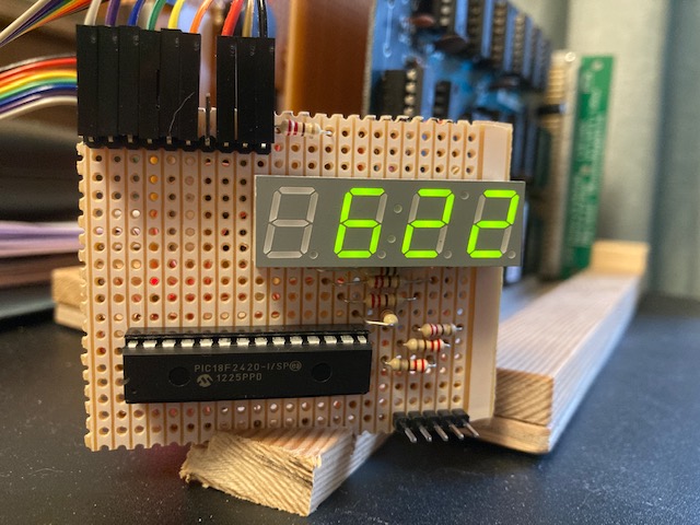
One of the reasons for adding the RTC was so the computer could sit on my work desk as a slightly over sized clock. The plan at the time was to use some sort of retro display type to compliment the age to the Z80 board. The trouble with this is that it would tie the processor up with driving a multiplex display not leaving much time it to do anything else. Coincidentally around this time I had an idea for another project which will need me to move data directly from a Z80 bus to a PIC. As a proof of concept for this I pulled together a simple 4 digit LED display driven from and 18F series PIC. Initially this is being driven via the a Z80 PIO port, the next stage will be to change it to connect directly to the processor data bus.
As currently configured every minute the RTC creates a Z80 interrupt which sets off an update of each clock digit to via the PIO. The PIC drives the multiplex display as a background routine with each PIO update causing a PIC interrupt to refresh the clock digit data. The net result is there is almost no additional load on the Z80 and I have a clock on my desk.
Where to from here?
Getting the retro Z80 board working and developing it has be great fun but in truth it is in not the best test test bed for the PIC interface I am designing. So for this I am building a R2014 ‘clone’ Z80 CPU board, more of this in the future. I will come back the Elektor computer to look at adding a the VDU card I mentioned in my last post, but I suspect this will end up being a Christmas project.


