Download presentation
Presentation is loading. Please wait.

1
FATIGUE

2
Ship Break

3
BOLT FAILURE .

4
.

5
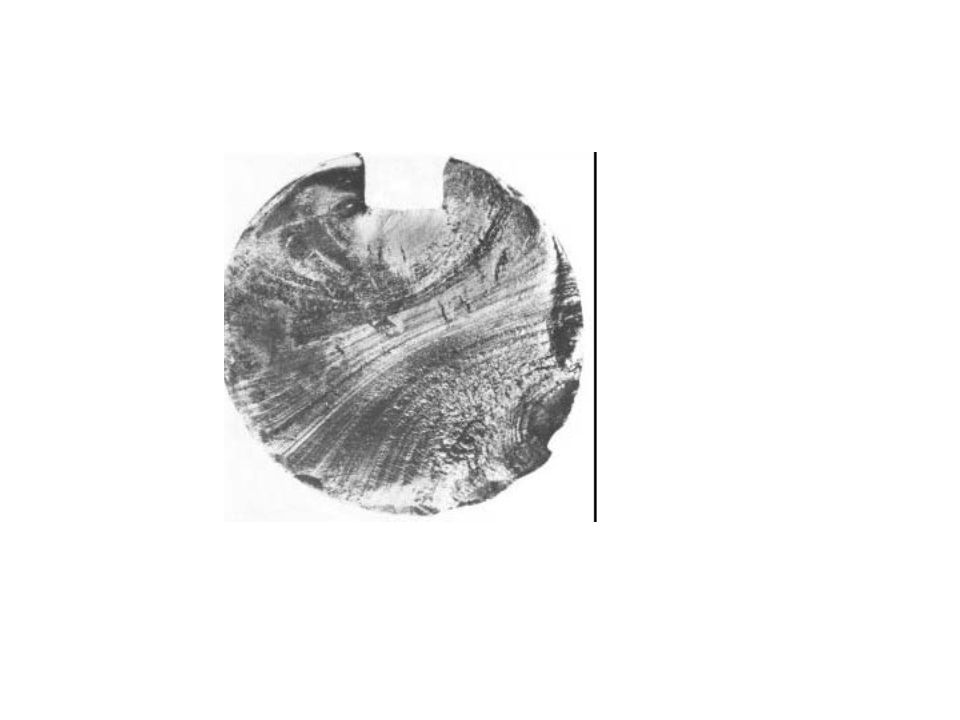
BEACH MARKS

6
Beach Marks of FATIGUE .

7
Examples of Bolt Failures M24 Engine Mounting Bolt Failure

8
Failure due to repeatedly applied load is known as Fatigue.
The physical effect of a repeated load on a material is different from the static load. Failure always being brittle fracture regardless of whether the material is brittle or ductile. Mostly fatigue failure occur at stress well below the static elastic strength of the material.

9
Fatigue It has long been known that a component subjected to fluctuating stresses may fail at stress levels much lower than its monotonic fracture strength, due to a process called Fatigue. Fatigue is an insidious time-dependent type of failure which can occur without any obvious warning. It is believed that more than 95 % of all mechanical failures can be attributed to fatigue. There are normally three distinct stages in the fatigue failure of a component, namely: Crack Initiation, Incremental Crack Growth, and the Final Fracture.

11
Fatigue Introduction : In several applications, components have to withstand different kinds of load at different times . Materials subjected to these fluctuating or repeated load tends to show a behavior which is different from what they show under steady loads.

12
Fatigue occurs at stress well within the ordinary elastic range as measured in the static tension test. Fracture resulting from fatigue is very difficult to predict and hence a good understanding of fatgue behavior is very important.

13
Types of fatigue loading:
1.Completely reversed cycle of stress: 2. repeated stress cycles 3. irregular or random stress cycle:

15
Completely reversed cycle of stress:
Illustrates the type of fatigue loading where a member is subjected to opposite loads alternately with a means of zero. For example bending of steel wire continuously in either direction leads to alternate tensile and compressive stresses on its surface layers and failure fatigue.

16
If the applied load changes from any magnitude in one direction to the same magnitude in the opposite direction, the loading is termed completely reversed,

17
Repeated stress cycles:
Type of fatigue loading where a member is subjected to only tension but to various degrees. A spring subjected to repeated tension as in a toy would lead to fatigue failure.

18
Irregular or random stress cycle:
This type of fatigue loading where a member could be subjected to irregular loads just as in the case of an aircraft wing subjected to wind loads.

19
i.e if the load changes from one magnitude to another (the direction does not necessarily change), the load is said to be fluctuating load.
, the load is said to be fluctuating load.")
20
Stages of fatigue failure
consider a ductile material which is subjected to simple alternating tensile and compressive stresses. Failure by fatigue is found to take place in three stages: i) Crack nucleation ii) Crack growth iii) Fracture
 Crack nucleation. ii) Crack growth. iii) Fracture.")
22
Crack nucleation: During the first few cycles of loading, localized changes take place in the structure at various places within the material. These changes lead to the formation of submicroscopic cracks.

23
Low Cycle Fatigue Based on the LCF local strain philosophy, fatigue cracks initiate as a result of repeated plastic strain cycling at the locations of maximum strain concentration.

24
These cracks are usually formed at the surface of the specimen.
There are several theories like orowans theory, cottell & hull theory etc, which explain the mechanism of crack nucleation.

25
Crack growth: The submicroscopic cracks formed grow as the cycles of loading continue and become microscopic cracks.

26
Fatigue Crack Propagation
If a crack exists in the component before it goes into service, for example due to weld fabrication or from some other cause, the ‘initiation’ stage is by-passed and the fatigue failure process is taken up entirely with incremental growth and final fracture.

27
Most fatigue failures in practice are in the low stress region, much less than the yield stress,
where the LEFM is likely to be valid. Hence, the LEFM principles can be applied to predict incremental fatigue crack propagation

29
Fracture: When critical size is reached, the cark propagates. The are of cross-section supporting the load gets reduced thus increasing the stress value and finally occurs.

31
Classical Fatigue The classical approach to fatigue, also referred to as Stress Controlled Fatigue or High Cycle Fatigue (HCF), through S/N or Wöhler diagrams, .
, through S/N or Wöhler diagrams, .")
32
In order to determine the strength of materials under the action of fatigue loads, specimens with polished surfaces are subjected to repeated or varying loads of specified magnitude while the stress reversals are counted up to the destruction point. The number of the stress cycles to failure can be approximated by the WOHLER or S-N DIAGRAM,

33
WOHLER or S-N DIAGRAM,

34
Fatigue properties : Fatigue life (N): it is total number of cycles are required to bring about final fracture in a specimen at a given stress. Fatigue life for a given condition is a property of the individual specimen and is arrived at after testing a number of specimens at the same stress.

35
Fatigue life for P % survival (Np)
It is fatigue life for which P percent of samples tested have a longer life than the rest. For example, N90 is the fatigue life for which 90% of the samples would be expected to survive and 10% to fail at a particular stress.

36
Median fatigue life: it is fatigue life for which 50 % of the population of samples fail and the other 50 % survive at a particular stress.

37
OR it is the strength of a material for a particular fatigue life.
Fatigue strength (σn) It is stress at which a material can withstand repeatedly N number of cycles before failure. OR it is the strength of a material for a particular fatigue life.
 It is stress at which a material can withstand repeatedly N number of cycles before failure. OR it is the strength of a material for a particular fatigue life.")
38
Fatigue limit or Endurance limit (σE):
it is stress below which a material will not fail for any number of cycles. For ferrous materials it is approximately half of the ultimate tensile strength. For non-ferrous metal since there is no fatigue limit.

39
Endurance limit is taken to be the stress at which it endures, N number of cycles without failure .N is usually taken as 5 x 10⁸ cycles for non-ferrous metals.

40
Effect of stress concentration 2) Size effect: 3) Surface Roughness:
Factors affecting fatigue: Effect of stress concentration 2) Size effect: 3) Surface Roughness: 4) Surface Residual Stress: 5) Effect of temperature: 6) Effect of metallurgical variables;
 Size effect: 3) Surface Roughness: 4) Surface Residual Stress: 5) Effect of temperature: 6) Effect of metallurgical variables;")
41
It is most responsible for the majority of fatigue failures
Factors affecting fatigue: 1) EFFECT OF STRESS CONCENTRATION It is most responsible for the majority of fatigue failures All m/c elements contain stress raisers like fillets, key ways, screw threads, porosity etc. fatigue cracks are nucleated in the region of such geometrical irregularities.
 EFFECT OF STRESS CONCENTRATION. It is most responsible for the majority of fatigue failures. All m/c elements contain stress raisers like fillets, key ways, screw threads, porosity etc. fatigue cracks are nucleated in the region of such geometrical irregularities.")
42
The actual effectiveness of stress concentration is measured by the fatigue strength reduction factor Kf Kf = σn / σnI σn = the fatigue strength of a member without any stress concentration σnI = the fatigue strength of the same member with the specified stress concentration.

43
fatigue failure by stress concentration can be minimized by
reducing the avoidable stress-raisers careful design and the prevention of stress raisers by careful machining and fabrication.

44
2) SIZE EFFECT: The strength of large members is lower than that of small specimens. This may be due to two reasons. The larger member will have a larger distribution of weak points than the smaller one and on an average, fails at a lower stress. Larger members have larger surface Ares. This is important because the imperfections that cause fatigue failure are usually at the surface.

45
Effect of size: Increasing the size (especially section thickness) results in larger surface area and creation of stresses. This factor leads to increase in the probability of crack initiation. This factor must be kept in mind while designing large sized components.

46
3) SURFACE ROUGHNESS: almost all fatigue cracks nucleate at the surface of the members. The conditions of the surface roughness and surface oxidation or corrosion are very important. Experiments have shown that different surface finishes of the same material will show different fatigue strength.

47
Plating, thermal or mechanical means to induce residual stress
Methods which Improve the surface finish and those which introduce compressive stresses on the surface will improve the fatigue strength. Smoothly polished specimens have higher fatigue strength. Surface treatments. Fatigue cracks initiate at free surface, treatments can be significant Plating, thermal or mechanical means to induce residual stress

48
4) SURFACE RESIDUAL STRESS:
Residual stresses are nothing but locked up stresses which are present in a part even when it is not subjected to an external force. Residual stresses arise during casting or during cold working when the plastic deformation would not be uniform throughout the cross section of the part.

49
Compressive residual stresses are beneficial, tension is detrimental
Residual stresses not permanent, can be relaxed (temp., overload)
")
50
Shot Peening • Surface of component blasted with high velocity steel or glass beads • Core of material in residual tension, surface in residual compression • Easily used on odd shaped parts, but leaves surface dimpling

51
Residual stresses can be either tensile or compressive when plastically deformed.
Those residual stresses help in the nucleation of cracks and their further propagation.

52
5) EFFECT OF TEMPERATURE:
Fatigue tests on metals carried out at below room temperature shows that fatigue strength increases with decreasing temperature. F.S as Temperature

53
Higher the temperature, lower the fatigue strength.
Stress amplitude No. of cycles to Failure

54
Temperature. Endurance limits increase at low temperature
(but fracture toughness decreases significantly) Endurance limits disappear at high temperature Creep is important above 0.5Tm (plastic, stress-life not valid)
 Endurance limits disappear at high temperature. Creep is important above 0.5Tm (plastic, stress-life not valid)")
55
Effect of metallurgical variables;
Fatigue strength generally increases with increase in UTS Fatigue strength of quenched & tempered steels (tempered martensitic structure) have better fatigue strength Finer grain size show better fatigue strength than coarser grain size. Non-metallic inclusions either at surface or sub-surface reduces' the fatigue strength
 have better fatigue strength. Finer grain size show better fatigue strength than coarser grain size. Non-metallic inclusions either at surface or sub-surface reduces the fatigue strength.")
56
Environmental Effects
Environment. Corrosion has complex interactive effect with fatigue (attacks surface and creates brittle oxide film, which cracks and pits to cause stress concentrations) Often in practice, there are modifying factors for the above applied to the equation for the endurance limit.
 Often in practice, there are modifying factors for the above applied to the equation for the endurance limit.")
57
Mechanisms of fatigue failure
Some of the theories which explain the mechanism of crank nucleation leading to fatigue fracture are mentioned below, Wood’s theory Orowan’s theory Cottrell and Hull theory

58
Wood’s theory: ‘slip’ takes place along certain crystallographic planes due to shear stresses acting along those planes. When an alternate load is applied, the direction of the shear stresses also changes alternately.

59
Wood’s theory: These causes back and forth slip moments in opposite directions. Slip bands are produced due to this systematic buildup of fine slip movements in either direction.

60
Wood’s theory: STATIC FATIGUE DEFORMATION

61
Wood’s theory: These slip movements are in the order of 1 nanometer, these slip bands are nothing but intrusions and extrusions formed on the surface of the specimen to form surface irregularities which are initiated as cracks.

62
Wood’s theory: Once the cracks are nucleated, growth of these cracks takes place continuously due to stress concentration before fracture occurs. Typical , the crack growth period accounts for 75-90% of the fatigue life in the part.

63
Orowans Polycrystalline Model theory:
Consider a polycrystalline sample consisting of a number of grains. Let A be one of the grains which is weaker then the surrounding grains. A

64
Orowans Polycrystalline Model theory:
When load is applied to this sample, grain A being weaker than the rest, yields in the directions of loading. When the load is reversed, grain A tries to yield in the opposite direction.

65
As the loads are continuously alternated.
Orowans Polycrystalline Model theory: As the loads are continuously alternated. Grain A continuously yields in opposite direction and faster than the rest of grains. This causes a relative movement between grains A and the surrounding grains and leads to the formation of fine submicroscopic cracks at the grain boundary of grain A.

66
Orowans Polycrystalline Model theory:
In a polycrystalline sample, there may be a number of such grains which may be weaker than their surrounding grains. Hence a number of submicroscopic cracks may be expected to form at their boundaries. Subsequent cycles of stresses helps in the coalescence of a number of submicroscopic cracks to form a bigger crack which may grow and result in fracture.

67
Orowans Polycrystalline Model theory:
In general fatigue cracks begins at the surface of the specimen, probably because the grains adjacent to the surface are less restricted than the surrounding grains. Therefore weak grains like grain A can be to be found next to the surface.

68
Cottrell and Hull Theory:
This theory is based on a model; involving interaction of edge dislocations on two slip systems. When two different slip systems work with different directions and planes then they produce slip at the surface forming intrusion and extrusion. These intrusions act as starting point of fatigue cracks. L T

69
2. Visualize load transfer from one part or section to another and the
Fatigue Design Guideline (minimize stress concentrations) Consider actual stresses, including stress concentrations, rather than to nominal average stresses. 2. Visualize load transfer from one part or section to another and the distortions that occur during loading to locate points of high stress 3. Avoid adding secondary brackets, fittings, handles, steps, bosses, grooves, and openings at locations of high stress
 Consider actual stresses, including stress concentrations, rather than to nominal average stresses. 2. Visualize load transfer from one part or section to another and the. distortions that occur during loading to locate points of high stress. 3. Avoid adding secondary brackets, fittings, handles, steps, bosses, grooves, and openings at locations of high stress.")
70
4. Use gradual changes in section and symmetry of design to reduce
secondary flexure 5. Consider location and types of joints (frequent cause of fatigue problems) 6. Use double shear joints when possible 7. Do not use rivets for carrying repeated tensile loads (bolts superior) 8. Avoid open and loosely filled holes
 6. Use double shear joints when possible. 7. Do not use rivets for carrying repeated tensile loads (bolts superior) 8. Avoid open and loosely filled holes.")
71
9. Consider fabrication methods, specify strict requirements when needed
10. Choose proper surface finishes, but not overly severe (rivet holes, welds, openings etc. may be larger drivers) 11. Provide suitable protection against corrosion 12. Avoid metallic plating with widely different properties than underlying material
 11. Provide suitable protection against corrosion. 12. Avoid metallic plating with widely different properties than. underlying material.")
72
13. Consider prestressing when feasible, to include shot peening and cold working
14. Consider maintenance, to include inspections, and protection against corrosion, wear, abuse, overheating, and repeated overloading 15. Avoid use of structures at critical or fundamental frequency of individual parts or of the structure as a whole (induces many cycles of relatively high stress) 16. Consider temperature effects.
 16. Consider temperature effects.")
73
Fatigue test - Fatigue testing machine:
In the simplest type of machine for fatigue testing, the load applied is of bending type. The test specimen may be of simply supported beam or a cantilever. In a R.R.Moore rotating beam type machine for a simply supported beam a specimen of circular cross-section is held at its ends in special holders and loaded through two bearings equidistant from the center of the span.

74
R R Moore reversed- bending fatigue test:
Fatigue failure in engineering materials are observed by conducting the fatigue test which involves the plotting of an S-N diagram. Equal loads on these bearings are applied by means of weights that produce a uniform bending moment in the specimen between the loaded bearings. A motor rotates the specimen.

75
R R Moore reversed- bending fatigue test:

76
One such test is the RR Moore reversed- bending fatigue testing machine.
Since the upper fibers of the rotating beam are always in compression while the lower fibers are in tension, it is apparent that a complete cycle of reversed stress in all fibers of the beam is produced during each revolution. A revolution counter is used to find- the number of cycles the specimen is repeatedly subjected to the load. For simply supported beam, maximum bending moment is at the center.

77
Specimens subjected to fatigue test are made to undergo fluctuating or opposite stresses.
One such test arranged is shown in fig. where specimen is bent with the help of weights as well as rotated. By this alternate tensile and compressive stresses are imposed on the various layers of the specimen.

78
A counter coupled to the motor counts the number of cycles to failure
A counter coupled to the motor counts the number of cycles to failure. The experiment could be conducted for different loads, and different number of cycles to fracture are noted to draw the S-N diagram.

79
Bending momentMb = FL and bending stress S = M b
z Where L is the length of the specimen and z is the sectional modulus. In rotating cantilever beam type, the specimen is rotated while a gravity load is applied to the free end by means of a bearing. For cantilever specimen the maximum bending moment is at the fixed end. . M :. Mb = FL and S =_b Z

Similar presentations


 deformation of a material with time under a constant stress. It is both.>")


>")


