3-wire Inductive Proximity Sensor | How to Read the Datasheet


In this article, we are going to show you how to navigate through some important specifications on a typical 3-wire Inductive Proximity Sensor datasheet.
We’re going to look at two 3-wire proximity sensor datasheet from 2 different vendors, Pepperl+Fuchs and Schneider Electric, and discuss the specifications which are common.
What is a 3-wire inductive proximity sensor?
Before we dive into 2 proximity sensor datasheet, we’re going to quickly review what a 3-wire inductive proximity sensor is, discuss the different output types, and look at the schematic symbol of a 3-wire inductive proximity sensor.
A 3-wire inductive proximity sensor is an electronic device that can detect ferrous (Fe) targets without any physical contact. When it detects that target, it operates an internal electronic switch. Because the sensor is an electronic device it requires a DC power source.

Proximity sensors are being used in industry today to replace devices such as mechanical limit switches.
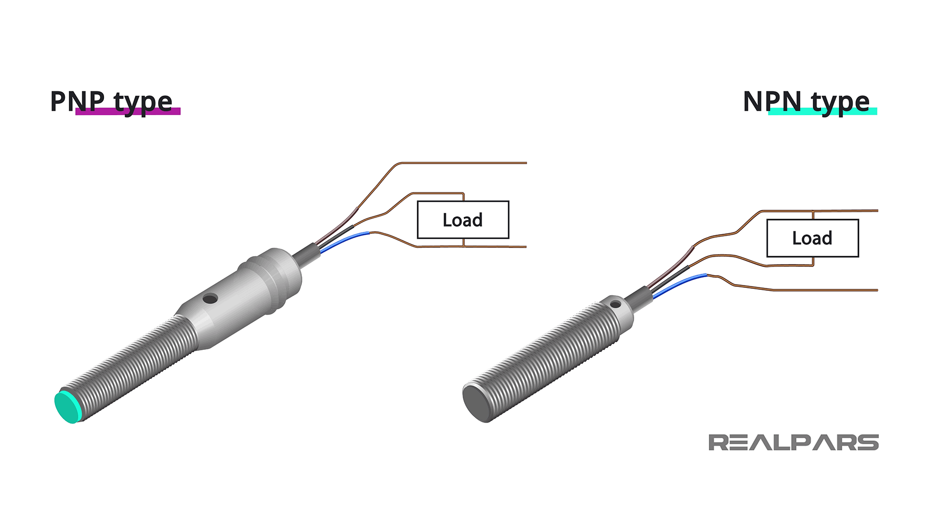
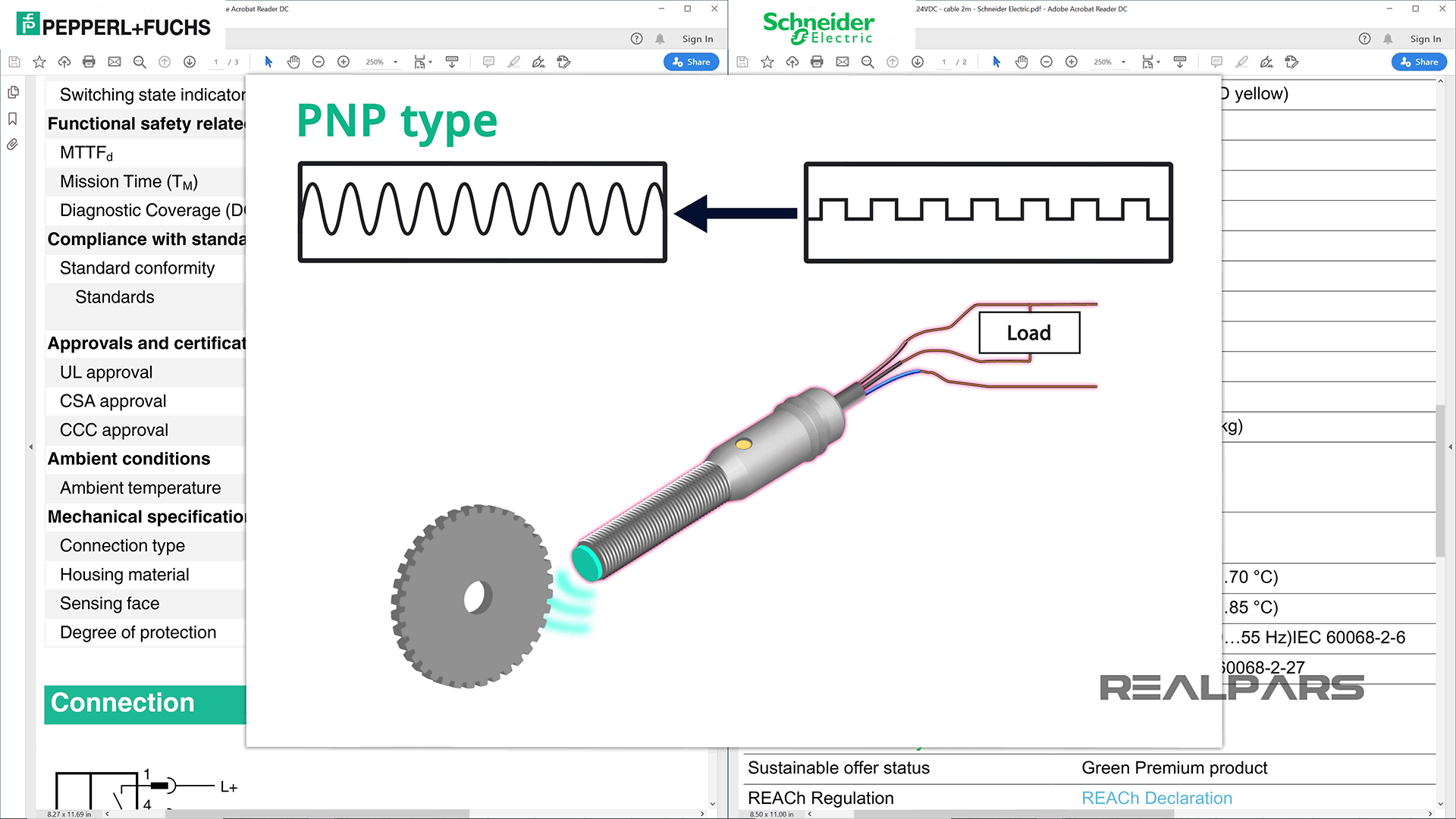
There are 2 different types of 3-wire Inductive Proximity Sensors NPN and PNP.
IEC proximity sensor symbol
The symbol that best illustrates the proximity sensor was developed by the International Electrotechnical Commission (IEC).
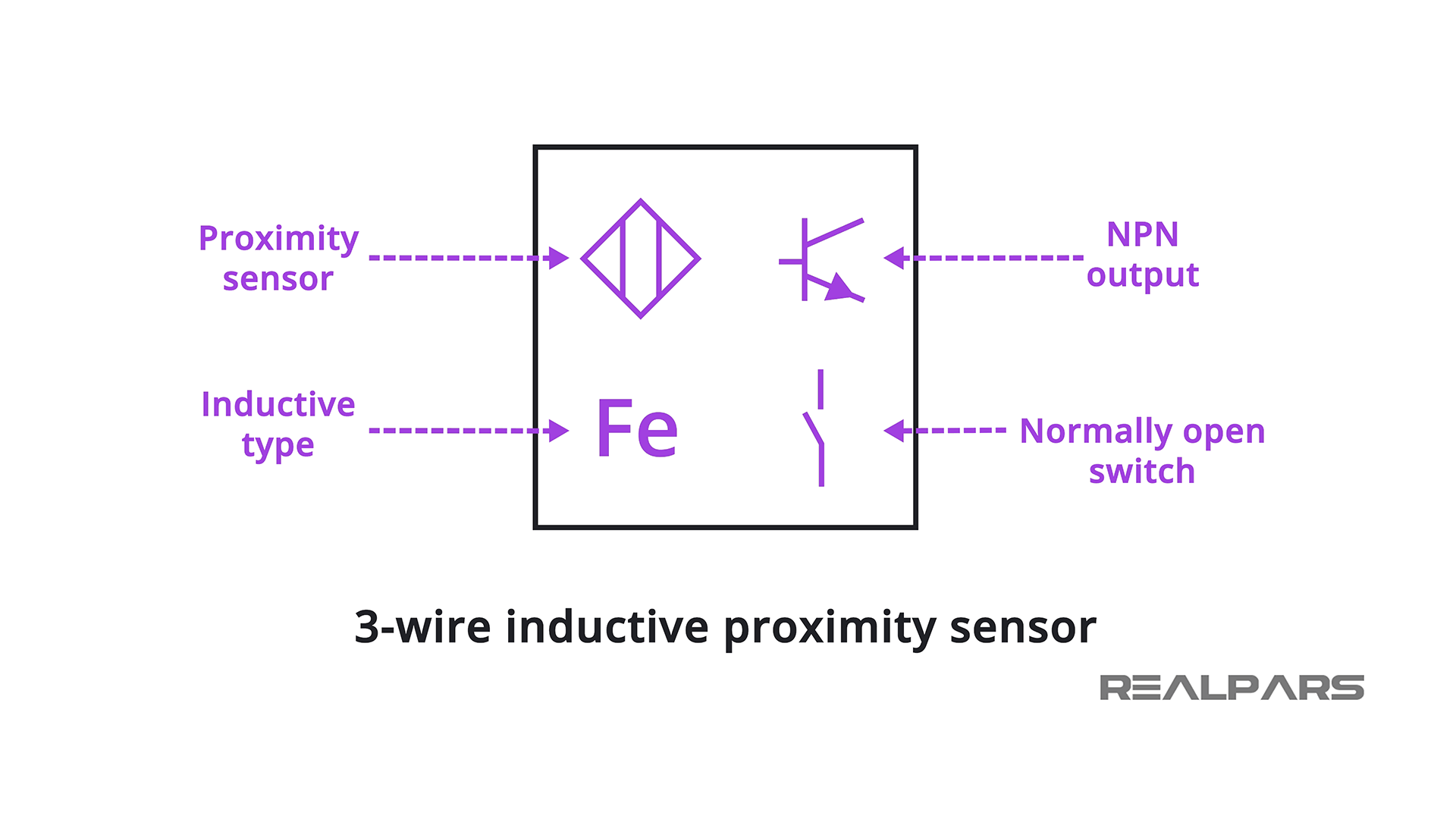
There are a number of figures inside the symbol representing the 3-wire inductive proximity sensor:
– The diamond indicates it is a proximity sensor
– Fe indicates that it is an inductive sensor
– The transistor indicates it is an NPN Output type
– The Normally Open Switch indicates that the internal electronic switch closes when the proximity sensor detects a target
3-wire proximity sensors datasheet
Ok, let’s look at 2 typical 3-wire inductive proximity sensor datasheet.
Inductive-sensor-XS108B3NAL2-SchneiderElectric
Inductive-sensor-NBB1.5-5GM25-E2-V3-PEPPERL_BFUCHS
Output Type specification
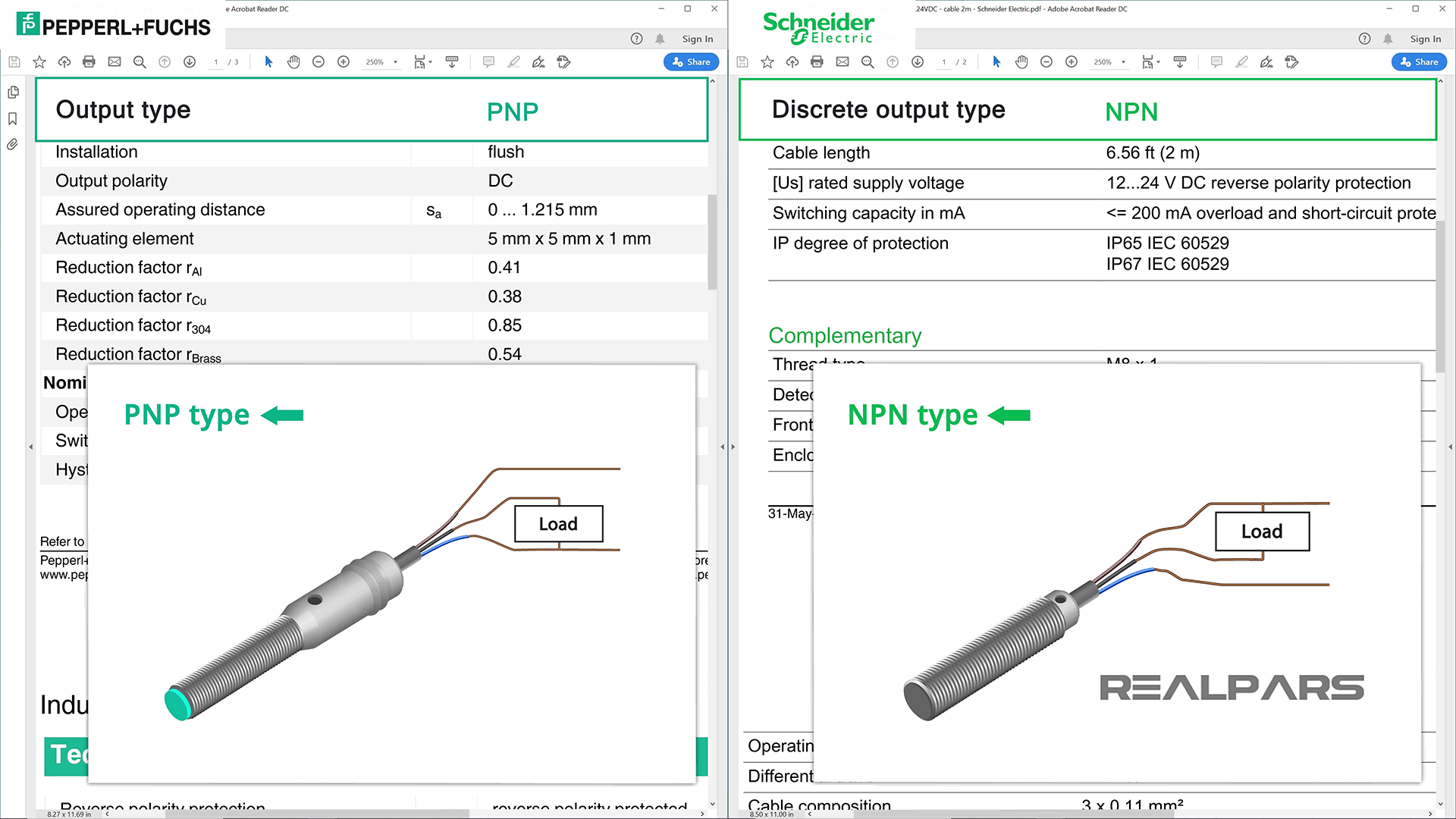
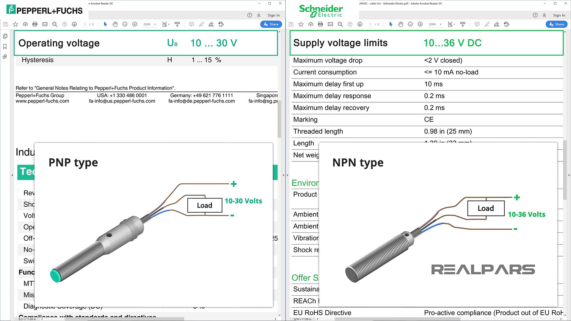
Let’s discuss the Output Type specification. The output type can be PNP or NPN which determines how the load is connected to the sensor.
Although they can both look identical physically, they are not interchangeable.
Operating Current or Switching Capacity
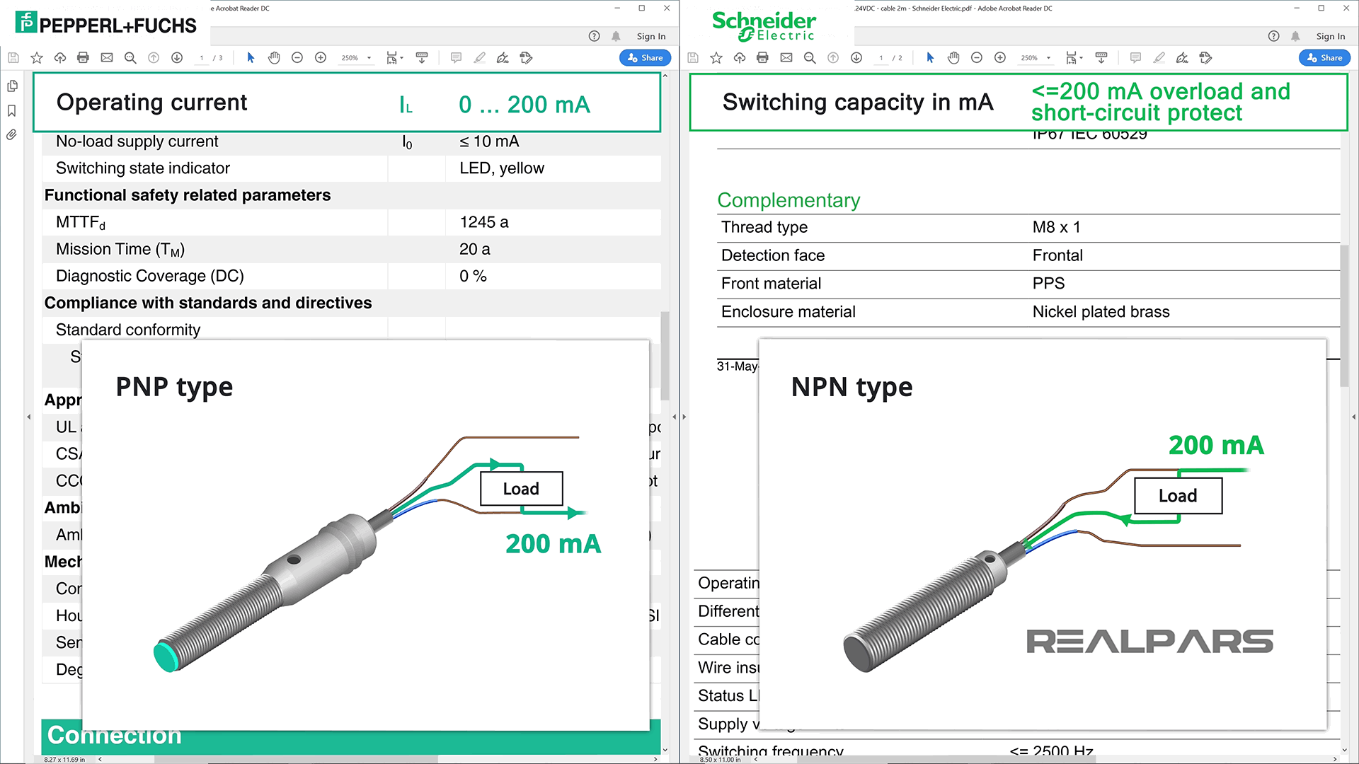
Operating Current or Switching Capacity in mA is another specification to discuss.
Unlike a mechanical limit switch or other similar devices, a proximity sensor can only carry a low amount of current before being damaged.
For these sensors, the maximum current allowed is 200 mA.
Operating Voltage or Supply Voltage Limits
An important specification is Operating Voltage or Supply Voltage Limits.
As discussed earlier, the 3-wire proximity sensor is an electronic device and requires a DC Power Supply.
Sensor datasheets will always provide a range of Power Supply voltages in which the sensor will operate as designed.
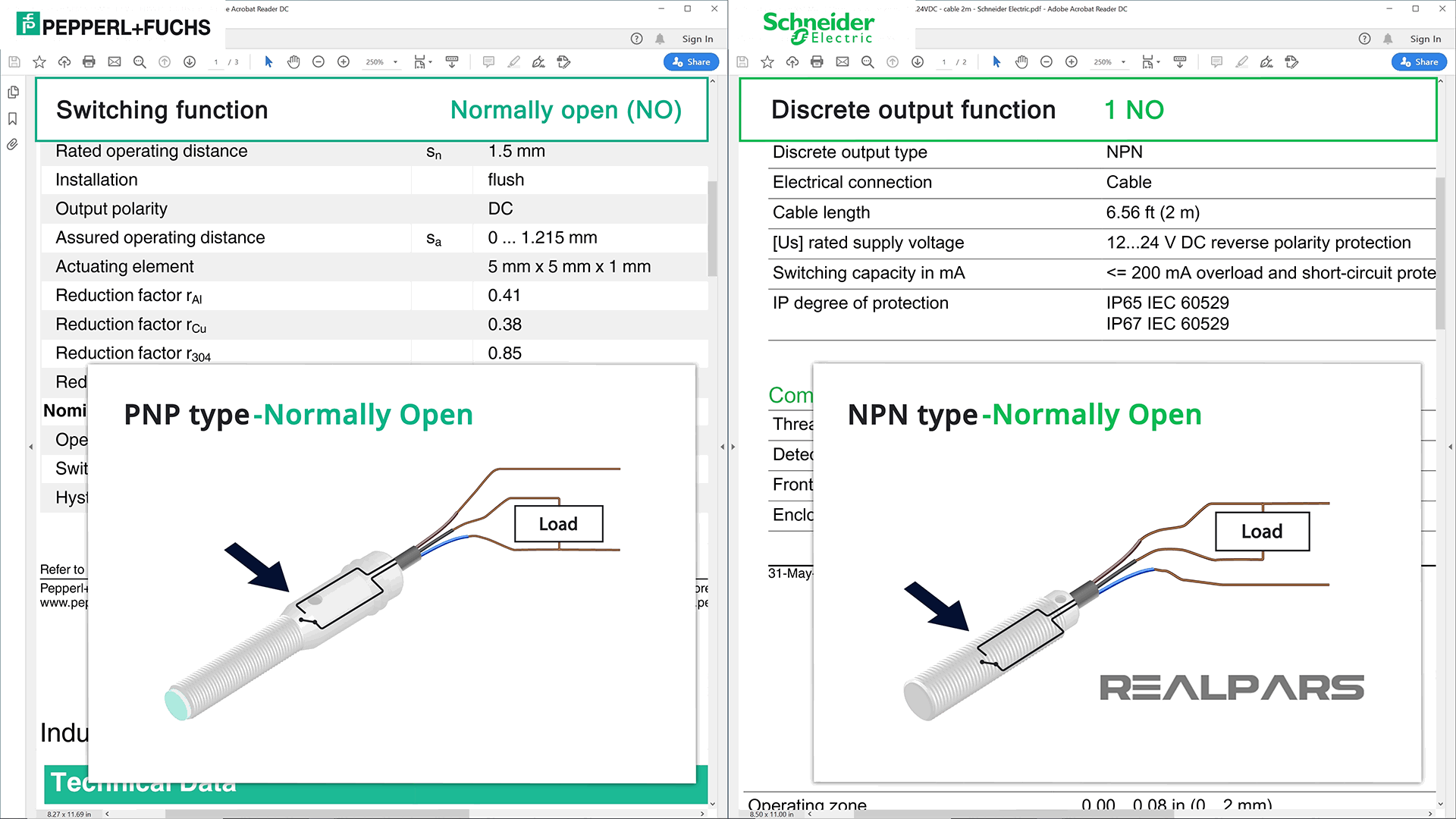
Switching Function or Discrete Output Function
Let’s look at the Switching Function or Discrete Output Function specification.
Just like any switch, proximity sensors can have Normally Open (NO) or Normally Closed (NC) contacts.
This datasheet specification indicates the state of the switch before it is activated.
Voltage Drop or Maximum Voltage Drop
Another important specification is the Voltage Drop or Maximum Voltage Drop.
Most of us assume that a closed switch will have zero volts dropped across it when it is closed. In most cases this is true.
Unfortunately, in the world of electronic proximity sensors, this is not the case.

This datasheet specification indicates how much voltage could be dropped across the proximity switch when it is closed. This may or may not be an issue, but be aware that a voltage loss will occur.

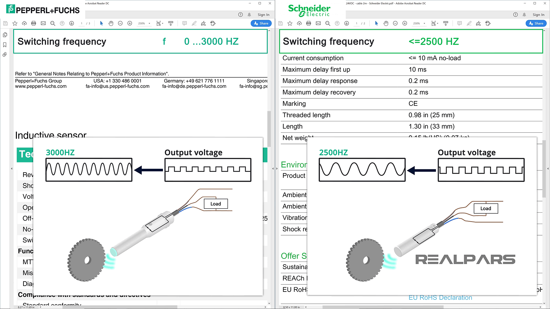
Switching Frequency
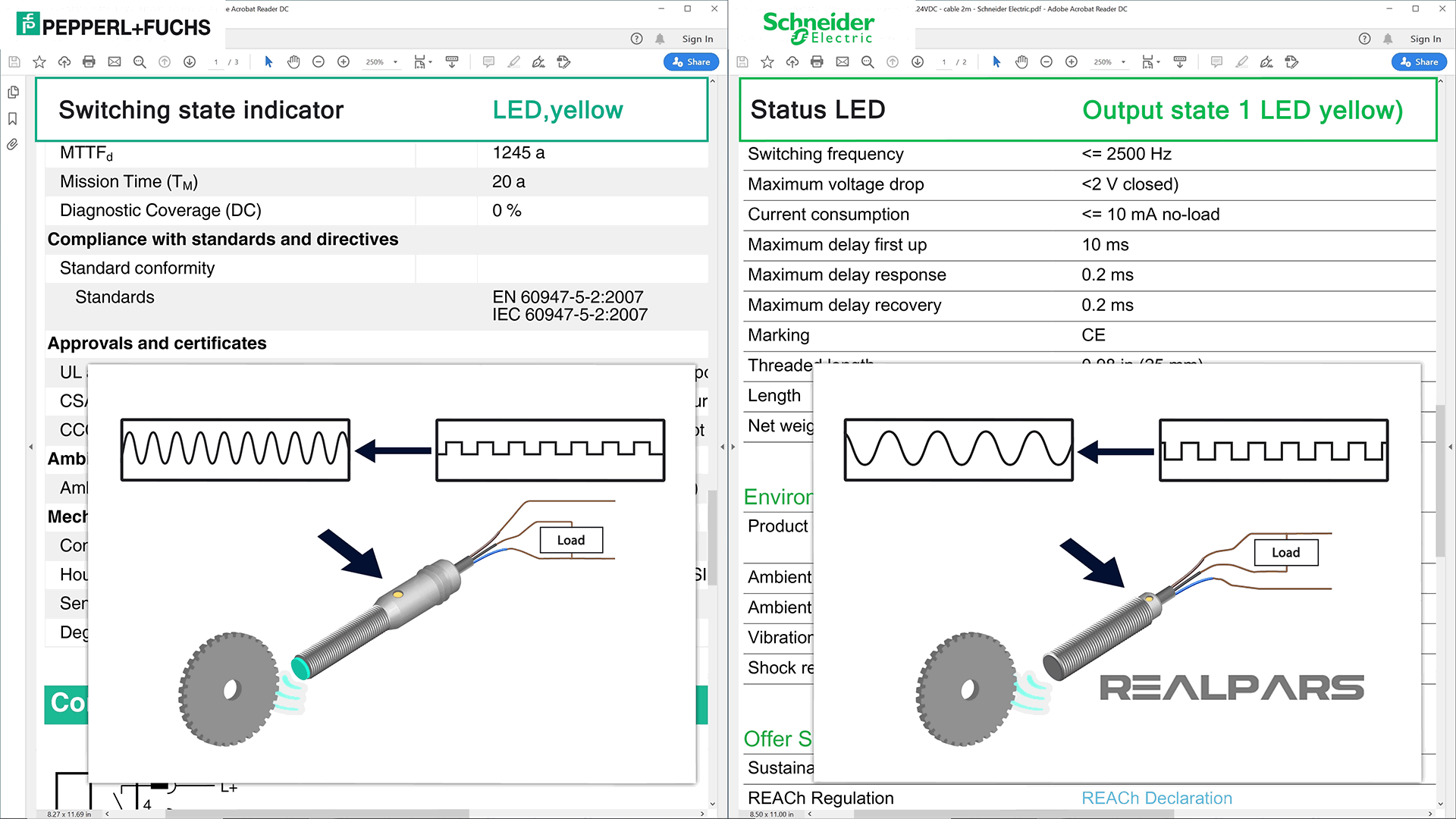
Another specification to consider is Switching Frequency.
Every time the target gets close to the proximity sensor, the internal switch operates and creates a voltage pulse.
Is it possible to use the proximity sensor to measure speed?
It is not intended for this purpose but perhaps at low speeds. Each time a gear tooth passes the sensor, a voltage pulse is created.
The speed or RPM of the geared wheel is determined by converting the pulse train frequency.
A proximity sensor has a switching frequency specification which limits its use to measure speed. There are sensors designed for speed measurement that operate exactly as proximity sensors.
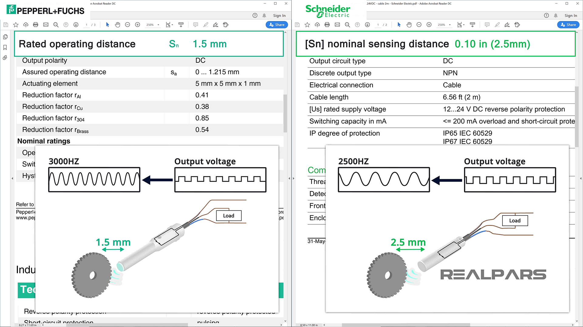
Rated Operating Distance or Nominal Sensing Distance
An important specification is the Rated Operating Distance or Nominal Sensing Distance.
Simply stated, it is the distance under ideal conditions that the sensor can detect the target and successfully operate its internal switch. Keep in mind that this specification does not take into account external conditions such as voltage supply and temperature.
Switching State Indicator or Status LED
Let’s talk about the specification called Switching State Indicator or Status LED.
Almost every vendor will have an LED indicator of some kind as part of the physical body of the proximity sensor.
The purpose of the LED is to indicate when the proximity sensor is activated.
Be careful because the LED will come on even if the load is connected incorrectly.
Summary
In review, vendors use slightly different names for proximity sensor specifications on datasheets.
Fortunately, similarities assist us in determining the important values we need to use and troubleshoot them correctly.
You might want to review 2 of our other articles:
How to Wire Discrete DC Sensors to PLC – Part 1
How to Wire Discrete DC Sensors to PLC – Part 2
Want to Learn More?
If you would like to get additional training on a similar subject please let us know in the comment section.
Check back with us soon for more automation control topics.
Got a friend, client, or colleague who could use some of this information? Please share this article.
The RealPars Team

Learn from Industry Experts
With a 7-day trial, then €25/month