Parametric Analysis of Tensegrity Plate-Like Structures: Part 1—Qualitative Analysis


Faculty of Civil Engineering and Architecture, Kielce University of Technology, 25-314 Kielce, Poland
*
Author to whom correspondence should be addressed.
Appl. Sci. 2020, 10(20), 7042; https://doi.org/10.3390/app10207042
Submission received: 16 September 2020
/
Revised: 29 September 2020
/
Accepted: 1 October 2020
/
Published: 11 October 2020
(This article belongs to the Section Mechanical Engineering)
Abstract
:Featured Application
A qualitative analysis of tensegrity structures is the first step to understand their unique properties, which allow for the control of static and dynamic parameters. The obtained results can be used in the design process of standard tensegrity building structures, i.e., plates and non-standard applications. The tensegrity concept can be used in the design of complex and intelligent structures with self-control, self-diagnosis, self-repair and active control. New and future potential applications will involve tensegrity-inspired metamaterials with exceptional mechanical properties.
Abstract
The study includes parametric analysis of special spatial rod grids called tensegrity plate-like structures. Tensegrity structures consist of only compression and tension components arranged in a system, whose unique mechanical and mathematical properties distinguish them from conventional cable–strut frameworks. Complete analysis of tensegrity structures is a two-stage process. The first stage includes the identification of self-stress states and infinitesimal mechanisms (qualitative analysis). The second stage focuses on the behaviour of tensegrities under external loads (quantitative analysis). In the paper, a qualitative analysis of tensegrity plate-like structures built with modified Quartex modules was conducted. Starting from a single-module structure, more complex cases were sequentially analysed. The different ways of plate support were considered. To carry out a qualitative assessment, a spectral analysis of the truss matrices and singular value decomposition of the compatibility matrix were used. The characteristic features of tensegrity structures were identified. On this basis, the plates were classified into one of the four groups defined in the paper, i.e., ideal tensegrity, “pure” tensegrity and structures with tensegrity features of class 1 or class 2. This classification is important due to different behaviours of the structure under external actions. The qualitative analysis carried out in the paper is the basis for a quantitative analysis.
1. Introduction
Tensegrity is a term derived from the English language as a compound of two words: “tension”—stretching, and “integrity”—stability. The term describes structures composed only of compressed (struts, rods) and tensed elements (cables). Although tensegrities are rod-like structures, some specific mechanical and mathematical properties distinguish them from conventional systems. The components are in a self-equilibrium system of internal forces called the self-stress state. In the absence of self-stress, the tensegrity structures are unstable, in other words, geometrically variable. Stabilisation occurs only after introducing initial stresses. Their modification allows for the control of the static parameters of the structure, among others [1,2,3,4,5].
One of the multitudes of applications of the tensegrity principle in civil engineering are double-layer grids. Generally, the elements of a double-layer grid are organised into two parallel planes, which are connected by vertical and diagonal elements. In the horizontal projection, the elements are arranged in a regular pattern. Double-layer tensegrity grids (also called tensegrity plate-like structures or tensegrity plates) are usually built from basic tensegrity modules such as Simplex [6,7,8,9,10,11,12,13] or Quartex [6,14,15,16,17,18]. Adjacent modules in tensegrity plates can be connected in a contiguous configuration (struts are connected to each other) or a non-contiguous configuration (maintaining a discontinuous arrangement of compressed elements). Modules can be connected edge-to-edge, node–node or strut–cable.
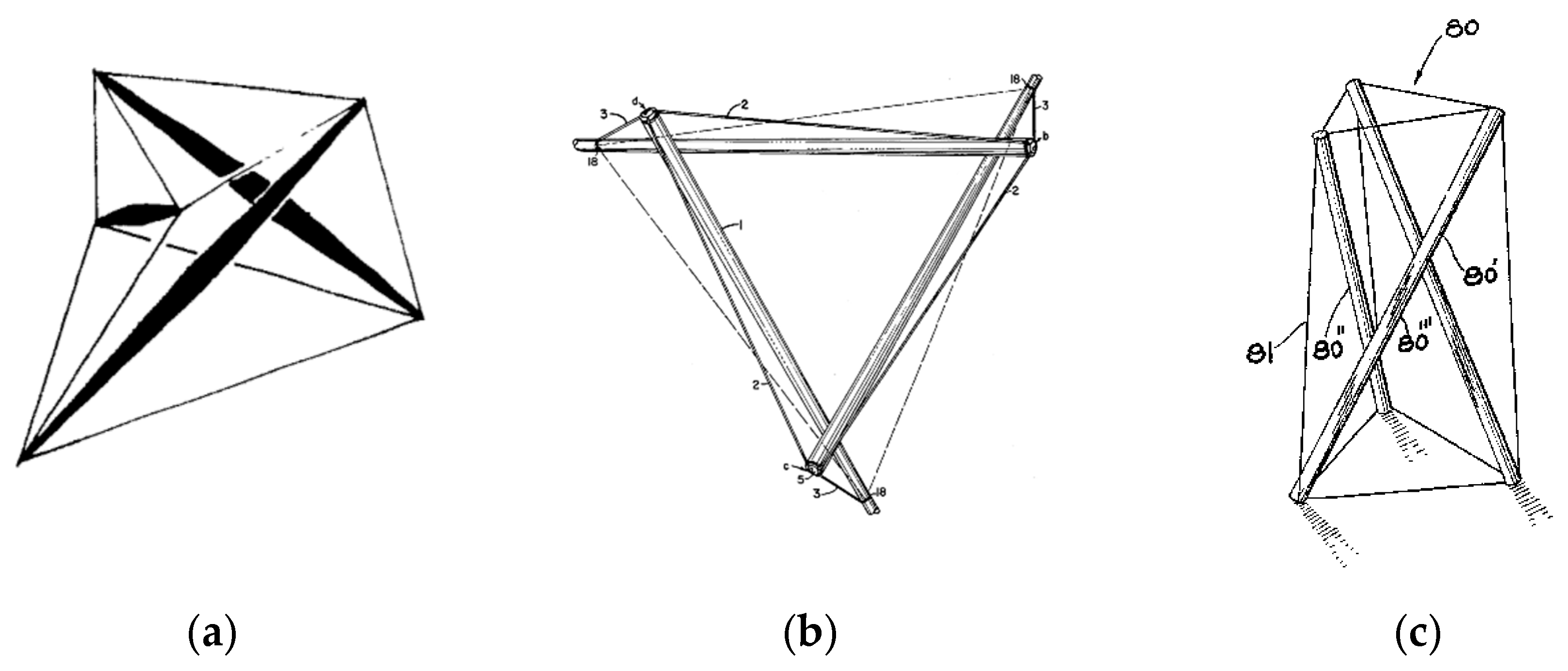
The first two-layer tensegrity grids were constructed by David Emmerich. In the patent [6], Emmerich proposed a structure consisting of modified Simplex modules with node–node connections and two structures built with Quartex modules linked edge-to-edge. A similar design was found by Fuller [7] and Snelson (Snelson’s patent was rejected) [8] (Figure 1). Both of the abovementioned modules, i.e., Simplex and Quartex, are most often used to build tensegrity plate-like structures.
An analysis of plates composed of Simplex modules was carried out, among others, by Kono and Kunieda [19], Gomez-Jauregui et al. [20] and Olejnikova [21]. Kono and Kunieda created the first experimental model of the tensegrity plate. It was built with thirty-three modified Simplex modules. The span of the structure was 9 m, and its area was 80 m2. Skelton and Oliveira compared the properties of tensegrity structures created from the same modules, but connected in different ways. The Gomez-Jauregui team proposed a method of obtaining tensegrity panels based on the geometry of traditional double-layer trusses, while Olejnikova studied constructions with single and double curvatures.
Tensegrity plates composed of Quartex modules were considered, among others, by Wang and Xu [22], Faroughi and Lee [23] and Sulaiman et al. [24] (Figure 2). Wang and Xu used semidefinite programming (SDP) to determine the optimal topology of the tensegrity plate-like structure consisting of nine modules. Faroughi and Lee used a genetic algorithm to optimise the cross-sections of cables and struts of a structure composed of twenty modules, whereas Sulaiman et al. considered the application of double-layered tensegrity grids consisting of four or eight modules as roofing.
A lot of papers about tensegrity plates are authored by Wang [15,25,26]. Wang proposed many tensegrity plate-like structures composed of Quartex modules connected together in various ways. Wang used other tensegrity modules to build plates as well. He presented numerous interesting examples of tensegrity plate-like structures built from regular or modified octahedron modules. Wang also proposed a temporary tensegrity plate-like structure, which could be folded and unfolded if necessary.
Israeli researcher Ariel Hanaor had a great impact on the development of research on tensegrity plates [27,28,29,30,31]. Hanaor tested how to combine basic tensegrity modules to obtain systems with sufficient rigidity and optimal features in terms of weight. He presented a geometrically rigid two-layer tensegrity grid and, like Wang, proposed the use of tensegrity plates as temporary structures.
Two-layer tensegrity grids were also widely investigated by Motro and Averseng with their teams. The aim of the French scientists’ research was to confirm the possibility of the application of tensegrity structures in engineering structures [14,32,33,34,35,36,37]. An experimental structure model consisting of nine modified Quartex modules was built. As part of the Tensarch project, which was the main part of Raducan’s dissertation, an experimental model of a tensegrity board consisting of 2V expander modules was created [14,33,34]. Averseng also considered similarly structured plates. Averseng, Jamin and Quirant proposed the use of tensegrity plates consisting of 2V expander modules as a temporary structure for people with reduced mobility [35,36,37].
Other interesting concepts of two-layer tensegrity grids have been presented by Papantoniou [38]. The models were built with modified Quartex modules and described on complicated geometric solids.
Apart from standard applications of tensegrity plates, non-standard ones can be found. Interesting proposals of using double-layered tensegrity grids were presented by Al Sabouni-Zawadzka and Gilewski [39,40,41] (Figure 3). In the paper [39], the researchers presented the concept of modeling tensegrity plates as a continuous model. This approach was also used by Obara [4,5]. Al Sabouni-Zawadzka and Gilewski additionally proposed the use of tensegrity plate-like structures built with Simplex and Quartex modules as intelligent constructions [40] and structures of metamaterials [41]. As in the works of Al Sabouni-Zawadzka and Gilewski, the use of tensegrity in the context of intelligent construction was dealt with by Fest, Shea and Smith [42,43]. They proposed the concept of a plate built with three or five adjustable tensegrity star modules.
The abovementioned examples are theoretical or experimental works. However, there are also practical applications of tensegrity plates in civil engineering. The most famous and the most spectacular example of a two-layer tensegrity grid was the Blur Building pavilion [44,45,46], created as a temporary structure for Expo 2012 in Switzerland (Figure 4a). The structure was created from octahedron modules with additional cables connecting the top surface. The tensegrity structure was also used as the roofing of a bank annex patio in Athens [47] (Figure 4b). A similar construction is used as the roofing of the exhibition pavilion in Patras, Greece [47] (Figure 4c). Other suggestions for the application of tensegrity plates in real engineering constructions can be found, for example, in [48,49].
The review of the literature showed that the vast majority of works are devoted mainly to the search for geometrical configuration, control of the shape of tensegrity structures under the influence of external loads and the application of these structures. The parametric analysis, determining the influence of self-stress states on the static properties of these structures, has been developed slightly. It should be noted that complete parametric analysis of tensegrity structures is a two-stage process. The first stage includes the identification of self-stress states and infinitesimal mechanisms (qualitative analysis), whereas the second stage focuses on the behaviour of tensegrities under external loads (quantitative analysis).
In this paper, the qualitative analysis is conducted. This analysis is the basis for a quantitative analysis. Tensegrity plate-like structures built with modified Quartex modules are considered. Starting from a single-module structure, more complex cases are sequentially analysed. The different methods of plates support are considered. To carry out a qualitative assessment, the spectral analysis of the truss matrices (compatibility matrix and stiffness matrix with the effect of self-equilibrated forces) is used, including the singular value decomposition (SVD) of the compatibility matrix. The characteristic features of tensegrity structures are identified. On this basis, the plates are classified into one of the four groups defined in the paper. This classification is important due to different behaviours of the structure under external actions.
2. Mathematical Description
The space truss finite element of Young’s modulus , cross-sectional area and length (Figure 5a) are used to model the components of the tensegrity structure. In a global coordinate system a finite element is described by the compatibility matrix :
where
Additionally, due to the existing self-stress state , the standard truss finite element description needs to be complemented with the geometric stiffness matrix :
The qualitative analysis is provided for an n-element space truss () described by the elasticity matrix :
with m degrees of freedom :
The compatibility matrix and the geometric stiffness matrix for tensegrity structures are determined using the finite element formalism [50,51,52,53,54,55,56,57,58,59]:
where is a Boolean matrix. It is assumed that the number of global degrees of freedom of each element corresponds to the number of global nodes of elements , as shown in Figure 5b. Consequently, the non-zero elements of can be expressed as .
The non-linearity equations of the equilibrium with the influence of the self-stress state in the structure can be written as:
where is the tangent stiffness matrix and is the linear stiffness matrix.
The qualitative analysis of tensegrity structures can be done through the singular value decomposition [60,61,62,63,64,65,66] of the compatibility matrix [58,67,68,69,70,71]. The singular value decomposition (SVD) of matrix is a factorisation in the form:
where and are orthogonal matrices and is a rectangular diagonal matrix. The SVD of matrix was described in depth in the paper [58], but to clarify, it should be remembered that the orthogonal matrices and , as well as matrix , are related to eigenvectors and eigenvalues of the following problems:
whose solutions can be expressed as:
Zero eigenvalues (if they exist) of the matrix (9)1 are related to the non-zero solution of homogeneous equations called self-stress, or more precisely, self-equilibrated normal forces that satisfy homogeneous equations of equilibrium. The self-stress can be considered as an eigenvector related to zero eigenvalue . However, zero eigenvalues (if any) of the matrix (9)2 are related to the finite mechanisms (rigid body motions) or infinitesimal mechanisms (local geometrical variability), which can be considered an eigenvector related to zero eigenvalue . In order to identify whether the mechanism is infinitesimal or finite, nonlinear analysis (7) with the use of the geometric stiffness matrix (6) should be applied. This is only if the self-stress exists. If the eigenvalues of are positive numbers, the mechanism is infinitesimal and the structure is stable. Zero eigenvalues are related to finite mechanisms, whereas a negative is responsible for instability of the structure.
The full solution to the eigen problem is provided by the spectral analysis of the tangent stiffness matrix , which takes into consideration the influence of the self-equilibrated forces:
Solutions of the eigen problem (11) can be expressed as:
3. Classification of Tensegrity Structures
In terms of structural mechanics, self-stress states and infinitesimal mechanisms stabilised by these states are the two most important features of tensegrity structures. Based on the definitions known from the literature, tensegrity structures demonstrate six characteristic features [58]:
- T — the structure is a truss,
- S — there is a self-stress state,
- C — tensile elements are cables and have no rigidity in compression,
- M — there is an infinitesimal mechanism stiffened by the self-stress state,
- I — the set of struts is contained within the continuous net of tensile elements,
- D — compressed elements form a discontinuous set so its extremities do not touch each other.
The structure has to meet the first three obligatory features (T, S, C) and at least one of the others (M, D, I) to be considered a structure with tensegrity features. If a structure meets all the above requirements, it can be classified as a “pure” tensegrity structure [3,45,57,70,71]. That classification was revised by Obara [70] (60–62) and extended to four classes, namely:
- ideal tensegrity—structures which meet all requirements (T, S, C, M, D, I) and all self-stress states (including the superposed one) must ensure the stability of the structure,
- “pure” tensegrity—structures satisfy the first five requirements, that is, T, S, C, M, D, and all self-stress states ensure the stability of the structure,
- structures with tensegrity features of class 1—structures meet the conditions of the first four features (T, S, C, M) and at least one self-stress state that ensures the stability of the structure,
- structures with tensegrity features of class 2—structures meet only the obligatory requirements (T, S, C) and additionally either feature I or D.
The classification is shown concisely in Table 1. Features S and M (the presence of self-stress states and infinitesimal mechanisms) can be determined directly by the spectral analyses of the truss matrices, while the features D, I, and C (struts do not share ends and are located inside the continuous net of tensile elements with zero compression rigidity) are recognised indirectly by the identified self-stress state.
The proposed classification systematises and precisely defines tensegrity structures and ensures the correct use of the term “tensegrity” in all applications. In engineering practice, such systematisation facilitates the analysis and design of tensegrities because it is a consequence of different behaviours of tensegrity structures under the influence of external action.
4. Examples
In this paper, the behaviour of structures built with modified Quartex modules is taken into account. Singular value decomposition of compatibility matrix and spectral analysis of tangent stiffness matrix are used for the analysis. Twenty-five structures are considered. For each structure, the following matrices are determined:
- —eigenvalues of matrix ,
- —eigenvectors of corresponding to the zero eigenvalues (if any) in responsible for the existence of the self-stress state (S),
- —eigenvalues of matrix ,
- —eigenvectors of corresponding to the zero eigenvalues (if any) in responsible for the existence of the mechanism (M),
- —eigenvalues of matrix .
Firstly, the single module is considered. Because the characteristic features of tensegrity structures do not depend on geometrical and mechanical characteristics, the constant longitudinal stiffness and constant lengths are assumed. The single modified Quartex module results are presented explicitly.
Next, more complex cases are analysed. Modules were joined in a contiguous configuration, i.e., in a way so that the ends of struts do not stay separated from each other. The bottom surfaces are connected edge-to-edge, the top ones connected node-to-node. The considered tensegrity plate-like structures are built with four, sixteen or sixty-four modules. A plate strip model is taken into account as well. The different methods of plates support are considered. For all proposed structures, the characteristic features of tensegrity structures are identified. On this basis, the plates are classified into one of the four groups defined in the paper, i.e., ideal tensegrity, “pure” tensegrity and structures with tensegrity features of class 1 or class 2. In the case of plates, due to the complexity of the results, only the number of self-stress states, the number of mechanisms and the classification of structures are shown in the paper. The calculation module was written in the Mathematica environment, owing to which operations were simplified by using functions and commands implemented there.
4.1. Single Modified Quartex Module
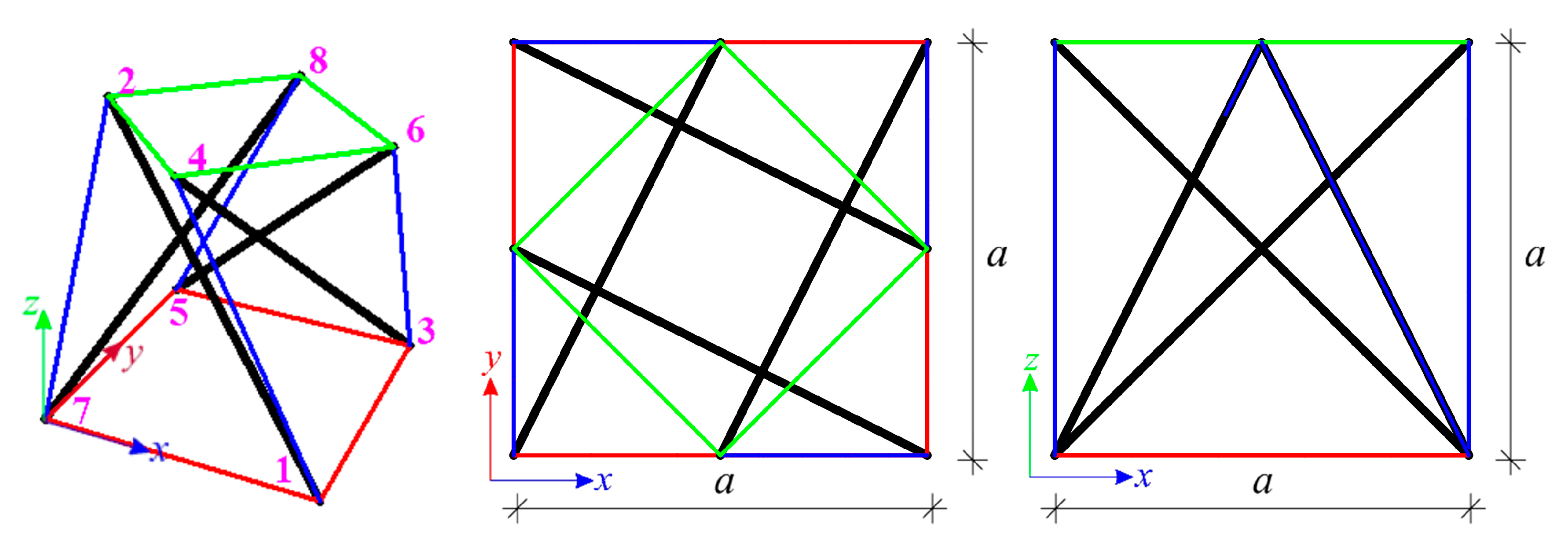
The first considered structure is the single modified Quartex module (Figure 6). The module consists of sixteen elements (n = 16), i.e., four struts and twelve cables, and eight nodes (w = 8). Its shape is based on a regular prism. The projection of the top surface of the modified Quartex module is inscribed into the bottom one, allowing for the easy connection of single units into multi-module structures [13,23,72,73,74,75]. The considered module’s dimensions allow it to fit into a unit cube. The coordinates of the nodes and the numbers of elements are shown, respectively, in Table 2 and Table 3.
The module with sixteen degrees of freedom (m = 16) is analysed. The blocked displacements are (Figure 7). As the number of elements and the number of degrees of freedom are equal (n = m = 16), the compatibility matrix is square, and, in turn, this means that the matrices and are equal and their eigenvalues are the same:
There is one zero eigenvalue in both matrices, thus one self-stress state and one mechanism is identified for the single module. The values of the eigenvector correlate to the zero diagonal value of the matrix , i.e., the self-stress forces (values are normalised in such a way that the maximum compressed force in struts is equal to ), are equal to:
and presented graphically in Figure 7. The values of the eigenvector , correlated to the zero diagonal value of the matrix , are the components of the displacement vector related to the mechanism and are equal:
In this case, the all eigenvalues of the tangent stiffness matrix are positive:
which confirms the stability of the module. It means the identified mechanism is infinitesimal. The infinitesimal mechanism of the modified Quartex is realised by the displacements of the top nodes (Figure 8 and Video S1). If the displacements of nodes 2, 4, 6, 8 are blocked, the mechanism would not exist.
The single modified Quartex module meets all tensegrity features, i.e., the structure is a truss (T) with a continuous net of tensile components—cables (C)—including the discontinuous set (D) of the compressed elements (I) and it features the existence of the self-stress state (S) and the mechanism (M). It means that it is classified as the ideal tensegrity.
4.2. Four-Module Tensegrity Plate-Like Structures
The structure built with four modified Quartex modules is considered (Figure 9a). The plate consists of 56 elements (n = 56) and 21 nodes (w = 21). Ten models with different methods of support, shown in Figure 9b, are considered:
- model P4-1—the truss (T) with 39 d.o.f. (m = 39),
- model P4-2—the truss (T) with 45 d.o.f. (m = 45),
- model P4-3—the truss (T) with 45 d.o.f. (m = 45),
- model P4-4—the truss (T) with 48 d.o.f. (m = 48),
- model P4-5—the truss (T) with 48 d.o.f. (m = 48),
- model P4-6—the truss (T) with 39 d.o.f. (m = 39),
- model P4-7—the truss (T) with 39 d.o.f. (m = 39),
- model P4-8—the truss (T) with 38 d.o.f. (m = 38),
- model P4-9—the truss (T) with 38 d.o.f. (m = 38),
- model P4-10—the truss (T) with 39 d.o.f. (m = 39).
For all analysed four-module models, the self-stress states (S) are identified—the models differ in the number of self-stress states. However, mechanisms (M) are identified only for five models, i.e., P4-1–P4-5. Model P4-1 is characterised by one mechanism, models P4-2, P4-4 and P4-5–by two mechanisms and model P4-3 by three mechanisms. None of the self-stress states correctly identifies the type of elements (that is, what is a strut and what is a cable) so for the last part of the analysis, superposed and normalised self-stress states for the single modified Quartex module is taken into account. All eigenvalues of the tangential stiffness matrix for models P4-1–P4-5 are positive and that confirms the stability of these plates. It means the identified mechanisms are infinitesimal. Other than the abovementioned characteristic features S and M, all models satisfy the requirements of characteristics T (plates are trusses) and C (tensile elements are cables and have no rigidity in compression). Models P4-1–P4-5 feature the presence of the mechanisms, so they can be classified as structures with tensegrity features of class 1. The feature D cannot be met because of the method of connecting modules. This feature does not occur for any of the structures presented in the paper. Due to lack of mechanisms, the other models, i.e., P4-6–P4-10, are qualified as structures with tensegrity features of class 2.
4.3. Sixteen-Module Tensegrity Plate-Like Structures
The plate consisting of sixteen modified Quartex modules is taken into account (Figure 10a). This structure consists of 212 elements (n = 212) and 69 nodes (w = 69). Six models, shown in Figure 10b, are considered:
- model P16-1—the truss (T) with 153 d.o.f. (m = 153),
- model P16-2—the truss (T) with 156 d.o.f. (m = 156),
- model P16-3—the truss (T) with 105 d.o.f. (m = 105),
- model P16-4—the truss (T) with 129 d.o.f. (m = 129),
- model P16-5—the truss (T) with 122 d.o.f. (m = 122),
- model P16-6—the truss (T) with 146 d.o.f. (m = 146).
For all models, self-stress states (S) exist. One mechanism (M) is identified for models P16-1 and P16-6. Only superposed self-stress states correctly identified elements. None of the eigenvalues of the tangential stiffness matrix for models P16-1 and P16-6 is non-positive, so the structures are stable and the identified mechanisms are infinitesimal. Except for the abovementioned features, all models are trusses (T) and their tensile elements are cables with no rigidity in compression (C). Models P16-1 and P16-6, due to the existence of the mechanism, are classified as structures with tensegrity features of class 1, while models P16-2–P16-5 satisfy the conditions of structures with tensegrity features of class 2 because of the absence of mechanisms.
4.4. Sixty-Four-Module Tensegrity Plate-Like Structures
Next, the structure built with sixty-four modified Quartex modules is taken into account (Figure 11a). The plate consists of 800 elements (n = 800) and 225 nodes (w = 225). Three models, shown in Figure 11b, are considered:
- model P64-1—the truss (T) with 579 d.o.f. (m = 579),
- model P64-2—the truss (T) with 621 d.o.f. (m = 621),
- model P64-3—the truss (T) with 621 d.o.f. (m = 621).
For all three models, self-stress states (S) exist. However, none of the self-stress states other than the superimposed one properly identifies tensile and compressed elements. One mechanism (M) is identified for each model. The identified mechanisms are infinitesimal and ensure the stability of the structure—the tangential stiffness matrix for all modes has no non-positive eigenvalues. All models also meet the requirements of features T and C—they are trusses with tensile elements that are cables and have no rigidity in compression. Both models satisfy the conditions of structures with tensegrity features of class 1.
For the sixty-four-module structure supported on two opposite edges (models P64-2 and P64-3), unlike the case the of the four-module structure (models P4-2 and P4-3), the change in the direction of support has no influence on the number of self-stress states. Both models feature 180 self-stress states and one mechanism.
4.5. Plate Strips
The last considered structures are plate strips. They are modelled like the four-module structures, presented in Figure 9a, with blocked displacements in the y direction in nodes 4, 6, 12, 16, 18 and 19. The structures consist of 56 elements (n = 56) and 21 nodes (w = 21). Five models (Figure 12) are taken into consideration:
- model PS-1—the truss (T) with 39 d.o.f. (m = 39),
- model PS-2—the truss (T) with 40 d.o.f. (m = 45),
- model PS-3—the truss (T) with 27 d.o.f. (m = 27),
- model PS-4—the truss (T) with 33 d.o.f. (m = 33),
- model PS-5—the truss (T) with 32 d.o.f. (m = 32).
All models feature self-stress states (S) but only for model PS-1 does a mechanism (M) exist. Only the superposed self-stress state identifies elements properly. The tangential stiffness matrix for model PS-1 has all positive eigenvalues. It means that the mechanism is infinitesimal and the structure is stable. All considered models satisfy the requirements of the characteristics T and C (structures are trusses and tensile elements are cables with zero rigidity in compression). Due to the occurrence of the mechanism, model PS-1 satisfies the conditions of structures with tensegrity features of class 1. The rest of the considered models, i.e., models PS-2–PS-5, are classified as having only tensegrity features of class 2 because of the lack of mechanisms. Comparing the analyses performed for the sixteen-module plate and plate strip, it can be noticed that the number of mechanisms obtained from the corresponding models (i.e., P16-1 and PS-1, P16-2 and PS-2, etc.) is equal.
5. Conclusions
The qualitative evaluation of truss structures presented in this paper was done for the assessment of the tensegrity plate-like structures. The qualitative analysis leads us to define the unique properties of tensegrities, which allow for the control of static and dynamic parameters. With regard to structural mechanics, the uniqueness of tensegrity structures lies in the existence of self-stress states (S) and mechanisms (M). The other features, i.e., the discontinuity of struts (D) and the inclusion of struts by tension elements (I), which are cables with no rigidity in compression (C), are determined indirectly by the identified self-stress state. Based on the presence of the characteristic tensegrity features T, S, C, M, D and I, a four-category classification was proposed. The structures were classified as ideal tensegrities, “pure” tensegrities and structures with tensegrity features of class 1 or 2.
Plates built with modified Quartex modules were considered. Starting from a single-module structure, more complex cases were sequentially analysed. The different methods of plates support were considered. The presence of self-stress states (S) and mechanisms (M) was determined by the singular value decomposition of the compatibility matrix. If any mechanism existed, the spectral analysis of the tangent stiffness matrix, which includes the self-stress state, was used to establish whether the mechanism was finite or infinitesimal. The compatibility matrix and the tangent stiffness matrix were determined using the finite element method. The geometrical and mechanical characteristics did not affect the peculiar tensegrity features, so all constants were assumed as a unit.
Results for all analysed plates are summarised in Table 4. The following conclusions were obtained:
- Only the single modified Quartex module is the ideal tensegrity. This module meets all tensegrity features, i.e., the structure is a truss (T) with a continuous net of tensile components—cables (C)—including a discontinuous set (D) of the compressed elements (I) and it features the existence of one self-stress state (S) and one mechanism (M).
- The plates built with four, sixteen or sixty-four modules cannot be the ideal tensegrities because of the way of connecting the modules. These structures do not satisfy the condition for the discontinuity of struts (D).
- All of the plates are characterised by the existence of more than one self-stress state (S). Due to the fact that only one self-stress state accurately identifies the elements, they cannot be considered as “pure” tensegrities. Actually, the only one appropriate self-stress state for the all considered plate-like structures is the one that is a superposition of the self-stress state of the single module.
- Considered plates can be classified as structures with features of class 1, if there is a mechanism, or class 2, if there is no mechanism (see Table 4).
The complete analysis of tensegrity structures is a two-stage process. The qualitative analysis carried out in the paper is the first stage and it is the basis for a quantitative analysis, which is the second stage. A quantitative analysis, which focuses on the behaviour of tensegrities under external loads, will be provided in part 2 of the paper. The proposed classification is important due to different behaviours of the structure under external actions. If a mechanism exists for the structure, that is when the structure is assigned to the one of the first three categories, and it is possible to control static properties, like, for example, stiffness, by the change in the self-stress level.
The proposed tensegrity plate-like structures can be used in the design process of standard tensegrity building structures, i.e., plates and non-standard applications. The tensegrity concept can be used in metamaterial unit cells and in deployable or smart engineering structures with monitoring, self-control, self-repair and active control.
Supplementary Materials
The following are available online at https://www.mdpi.com/2076-3417/10/20/7042/s1, Video S1: mechanism.
Author Contributions
Introduction was prepared by J.T. Definition of tensegrity and mathematical description were written by P.O. Results were obtained by J.T. The analysis of the results and conclusions were written by P.O. and J.T. All authors have read and agreed to the published version of the manuscript.
Funding
This research received no external funding.
Conflicts of Interest
The authors declare no conflict of interest.
References
- Gilewski, W.; Obara, P.; Kłosowska, J. Self-stress control of real civil engineering tensegrity structures. AIP Conf. Proc. 2018, 1922, 150004. [Google Scholar]
- Gilewski, W.; Kłosowska, J.; Obara, P. The influence of self-stress on the behavior of tensegrity-like real structure. MATEC Web Conf. 2017, 117, 00079. [Google Scholar] [CrossRef] [Green Version]
- Gilewski, W.; Kłosowska, J.; Obara, P. Parametric analysis of some tensegrity structures. MATEC Web Conf. 2019, 262, 10003. [Google Scholar] [CrossRef]
- Obara, P. Analysis of orthotropic tensegrity plate strips using a continuum two-dimensional model. MATEC Web Conf. 2019, 262, 10010. [Google Scholar] [CrossRef]
- Obara, P. Application of linear six-parameter shell theory to the analysis of orthotropic tensegrity plate-like structures. J. Theor. App. Mech. 2019, 57, 167–178. [Google Scholar] [CrossRef]
- Emmerich, D.G. Construction de Reseaux Autotendants. French Patent 1,377,290, 28 September 1964. [Google Scholar]
- Fuller, R.B. Tensile-Integrity Structures. U.S. Patent 3,063,521, 13 November 1962. [Google Scholar]
- Snelson, K. Continuous Tension, Discontinuous Compression Structures. U.S. Patent 3,169,611, 16 February 1965. [Google Scholar]
- Estrada, G.; Bungartz, H.-J.; Mohrdieck, C. Numerical form-finding of 2D tensegrity structures. In Proceedings of the 5th International Conference on Computation of Shell and Spatial Structures, Salzburg, Austria, 1–4 June 2005. [Google Scholar]
- Skelton, R.E.; de Oliveira, M.C. Tensegrity Systems; Springer: London, UK, 2009. [Google Scholar]
- Chen, Y.; Feng, J. Initial prestress distribution and natural vibration analysis of tensegrity structures based on group theory. Int. J. Struct. Stab. Dyn. 2012, 12. [Google Scholar] [CrossRef]
- Zhang, L.-Y.; Li, Y.; Cao, Y.-P.; Feng, X.-Q. Stiffness matrix based form-finding method of tensegrity structures. Eng. Struct. 2014, 58, 36–48. [Google Scholar] [CrossRef]
- Zhang, Q.; Zhang, D.; Dobah, Y.; Scarpa, F.; Fernando Fraternali, F.; Skelton, R. Tensegrity cell mechanical metamaterial with metal rubber. Appl. Phys. Lett. 2018, 113, 031906. [Google Scholar] [CrossRef] [Green Version]
- Motro, R. Tensegrity. Structural Systems for the Future; Kogan Page: London, UK, 2003. [Google Scholar]
- Wang, B.B. Free-Standing Tension Structures. From Tensegrity Systems to Cable-Strut System; CRC Press: New York, NY, USA, 2004. [Google Scholar]
- Ali, N.; Rhode-Barbarigos, L.; Smith, I. Analysis of clustered tensegrity structures using a modified dynamic relaxation algorithm. Int. J. Solids Struct. 2011, 48, 637–664. [Google Scholar]
- Zhang, L.; Gao, Q.; Liu, Y.; Zhang, H. An efficient finite element formulation for nonlinear analysis of clustered tensegrity. Eng. Comput. 2016, 33, 252–273. [Google Scholar] [CrossRef]
- Feron, J.; Boucher, L.; Denoël, V.; Latteur, P. Optimization of Footbridges Composed of Prismatic Tensegrity Modules. J. Bridge Eng. 2019, 24, 04019112. [Google Scholar] [CrossRef] [Green Version]
- Kono, Y.; Kunieda, H. Tensegrity grids transformed from double-layer space grids. In Conceptual Design of Structures, Proceedings of the International Symposium, Stuttgart, Germany, 7–11 October 1996; IASS: Stuttgart, Germany, 1996; pp. 293–300. [Google Scholar]
- Gómez-Jáuregui, V.; Arias, R.; Otero, C.; Manchado, C. Novel Technique for Obtaining Double-Layer Tensegrity Grids. Int. J. Solids Struct. 2012, 27, 155–166. [Google Scholar] [CrossRef]
- Olejnikova, T. Double Layer Tensegrity Grids. Acta Polytech. Hung. 2012, 9, 95–106. [Google Scholar]
- Wang, Y.; Xian, X. Prestress Design of Tensegrity Structures Using Semidefinite Programming. Adv. Civ. Eng. 2019, 2019, 1–9. [Google Scholar] [CrossRef]
- Faroughi, S.; Lee, J. Geometrical nonlinear analysis of tensegrity based on a co-rotational method. Adv. Struct. Eng. 2014, 17, 41–51. [Google Scholar] [CrossRef]
- Sulaiman, S.; Parthasarathi, N.L.; Geetha, B.; Satyanarayanan, K.S. The Performance of Half-Cuboctahedron Grid Tensegrity Systems in Roof Structures. Indian, J. Sci. Technol. 2016, 9, 1–6. [Google Scholar] [CrossRef]
- Wang, B.B. Cable-strut systems: Part I—Tensegrity. J. Constr. Steel Res. 1998, 45, 281–289. [Google Scholar] [CrossRef]
- Wang, B.B. Realizing Cable-Strut Systems. Int. J. Architect. Techn. 2012, 42, 42–53. [Google Scholar]
- Hanaor, A. Double-layer tensegrity grids: Static load response. II—Experimental study. J. Struct. Eng. 1991, 117, 1675–1684. [Google Scholar] [CrossRef]
- Hanaor, A. Aspects of design of double-layer tensegrity domes. Int. J. Space Struct. 1992, 7, 101–113. [Google Scholar] [CrossRef]
- Hanaor, A. Double-layer tensegrity grids as deployable structures. Int. J. Space Struct. 1993, 8, 135–145. [Google Scholar] [CrossRef]
- Hanaor, A. Geometrically rigid double-layer tensegrity grids. Int. J. Space Struct. 1994, 9, 227–238. [Google Scholar]
- Hanaor, A.; Liao, M.K. Double-Layer Tensegrity Grids: Static Load Response. Part I: Analytical Study. J. Struct. Eng. 1991, 117, 1660–1674. [Google Scholar] [CrossRef]
- Motro, R. Tensegrity Systems and Geodesic Domes. Int. J. Space Struct. 1990, 5, 341–351. [Google Scholar] [CrossRef]
- Raducanu, V.; Motro, R. New tensegrity grids. In Proceedings of the International Symposium on Theory, Design and Realization of Shell and Spatial Structures, Nagoya, Japan, 9–13 October 2001; pp. 320–321. [Google Scholar]
- Raducanu, V. Architecture et système constructif: Cas des systèmes de tenségrité. Ph.D. Thesis, Montpellier University, Montpellier, France, 2001. [Google Scholar]
- Averseng, J. Mise en œuvre et contrôle des systèmes de tenségrité. Ph.D. Thesis, Université Montpellier, Montpellier, France, 2004. [Google Scholar]
- Averseng, J.; Jamin, F.; Quirant, J. Système de tenségrité déployable et modulaire pour le développement de l’accessibilité. In Proceedings of the Rencontres Universitaires de Génie Civil, Nantes, France, 22–24 May 2017. [Google Scholar]
- Averseng, J.; Jamin, F.; Quirant, J. Les systèmes de tenségrité déployables: Application à l’accessibilité de la baignade en mer. In Proceedings of the Rencontres Universitaires de Génie Civil, Bayonne, France, 26–29 May 2015. [Google Scholar]
- Papantoniou, A. Parametric models of tensegrity structures with double curvature. ArchiDOCT 2017, 5, 63–76. [Google Scholar]
- Gilewski, W.; Al Sabouni-Zawadzka, A. On orthotropic properties of tensegrity structures. Procedia Eng. 2016, 153, 887–894. [Google Scholar]
- Gilewski, W.; Al Sabouni-Zawadzka, A. Smart tensegrity plate structures in communication engineering (in Polish). Logistyka 2014, 6, 1390–1399. [Google Scholar]
- Gilewski, W.; Al Sabouni-Zawadzka, A. Smart Metamaterial Based on the Simplex Tensegrity Pattern. Materials 2018, 11, 673. [Google Scholar]
- Fest, E.; Shea, K.; Domer, B.; Smith, I.F.C. Adjustable Tensegrity Structures. J. Struct. Eng. 2003, 129, 515–526. [Google Scholar] [CrossRef] [Green Version]
- Fest, E.; Shea, K.; Smith, I.F.C. Active tensegrity structure. J. Struct. Eng. 2004, 130, 1454–1465. [Google Scholar] [CrossRef] [Green Version]
- Crawfordt, L. Transgender Architectonics: The Shape of Change in Modernist Space; Routledge: London, UK, 2015. [Google Scholar]
- Gilewski, W.; Kłosowska, J.; Obara, P. Verification of Tensegrity Properties of Kono Structure and Blur Building. Procedia Eng. 2016, 153, 173–179. [Google Scholar] [CrossRef] [Green Version]
- Blur Building. Available online: https://dsrny.com/project/blur-building (accessed on 5 September 2020).
- Liapi, K.A.; Kim, J. Tensegrity Structures of Helical Shape: A Parametric Approach. In Proceedings of the Conference on Computation: The New Realm of Architectural Design, Istanbul, Turkey, 16–19 September 2009; pp. 53–58. [Google Scholar]
- Falk, A. Architectural and structural development of plate tensegrity. In Proceedings of the International Association for Shell and Spatial Structures 2006 Symposium, Beijing, China, 16–19 October 2006. [Google Scholar]
- Liapi, K.; Kim, J. A Parametric Approach to the Design of a Tensegrity Vaulted Dome for an Ephemeral Structure for the 2004 Olympics. In Proceedings of the the 2003 Annual Conference of the Association for Computer Aided Design in Architecture, Indianapolis, IN, USA, 24–27 October 2003; pp. 301–309. [Google Scholar]
- Bathe, K.J. Finite Element Procedures in Engineering Analysis; Prentice Hall: New York, NY, USA, 1996. [Google Scholar]
- Zienkiewicz, O.C.; Taylor, R.L. The Finite Element Method: The Basis; Elsevier Butterworth-Heinemann: London, UK, 2000; Volume 1. [Google Scholar]
- Gilewski, W.; Kasprzak, A. Introduction to mechanics of tensegrity modules. In Theoretical Foundation of Civil Engineering. Mechanics of Structures and Materials; Jemioło, S., Lutomirski, S., Eds.; OWPW: Warsaw, Poland, 2012; Volume 1, pp. 83–94. [Google Scholar]
- Calladine, C.R. Buckminster Fuller’s “tensegrity” structures and clerk Maxwell’s rules for the construction of stiff frames. Int. J. Solids Struct. 1978, 14, 161–172. [Google Scholar] [CrossRef]
- Calladine, C.R. Modal stiffnesses of a pretensioned cable net. Int. J. Solids Struct. 1982, 18, 829–846. [Google Scholar] [CrossRef]
- Pellegrino, S.; Calladine, C.R. Matrix analysis of statically and kinematically indeterminate frameworks. Int. J. Solids Struct. 1986, 22, 409–428. [Google Scholar] [CrossRef]
- Pellegrino, S. Analysis of prestressed mechanisms. Int. J. Solids Struct. 1990, 26, 1329–1350. [Google Scholar] [CrossRef]
- Calladine, C.R.; Pellegrino, S. First order infinitesimal mechanisms. Int. J. Solids Struct. 1991, 27, 505–515. [Google Scholar] [CrossRef]
- Obara, P.; Kłosowska, J.; Gilewski, W. Truth and myths about 2D tensegrity trusses. Appl. Sci. 2019, 9, 179. [Google Scholar] [CrossRef] [Green Version]
- Gilewski, W.; Kłosowska, J.; Obara, P. Form finding of tensegrity structures via Singular Value Decomposition of compability matrix. In Advances in Mechanics: Theoretical, Computational and Interdisciplinary Issues, Proceedings of the 21st International Conference on Computer Methods in Mechanics, Gdansk, Poland, 8–11 September 2015; CRC Press: Boca Raton, FL, USA, 2015; pp. 191–195. [Google Scholar]
- Golub, G.; Kahan, W. Calculating the singular values and pseudo-inverse of a matrix. J. SIAM Numer. Anal. Ser. B 1965, 2, 205–224. [Google Scholar] [CrossRef]
- Klema, V.C. The singular value decomposition: It’s computation and some applications. IEEE Trans. Autom. Contr. 1980, 25, 164–176. [Google Scholar] [CrossRef] [Green Version]
- Leon, S.J. Linear Algebra with Applications; Macmillan: New York, NY, USA, 1994. [Google Scholar]
- Long, C. Visualization of matrix singular value decomposition. Math. Mag. 1983, 56, 161–167. [Google Scholar] [CrossRef]
- Mc Guire, W.; Gallagher, R.H. Matrix Structural Analysis; Wiley: New York, NY, USA, 1979. [Google Scholar]
- Stewart, G.W. Matrix Algorithms: Basic Decompositions; SIAM: Philadelphia, PA, USA, 1998. [Google Scholar]
- Strang, G. Introduction to Linear Algebra; Wellesley-Cambridge Press: Wellesley, MA, USA, 1993. [Google Scholar]
- Gilewski, W.; Kłosowska, J.; Obara, P. Application of singular value decomposition for qualitative analysis of truss and tensegrity structures. ACTA Sci. Polon. Ser. Archit. 2015, 14, 3–20. [Google Scholar]
- Pellegrino, S. Structural computations with the singular value decomposition of the equilibrium matrix. Int. J. Solids Struct. 1993, 30, 3025–3035. [Google Scholar] [CrossRef]
- Rahami, H.; Kaveh, A.; Ardalan Asl, M.; Mirghaderi, S.R. Analysis of near-regular structures with node irregularity using SVD of equilibrium matrix. Int. J. Civ. Eng. 2013, 11, 226–239. [Google Scholar]
- Obara, P. Dynamic and Dynamic Stability of Tensegrity Structures; Wydawnictwo Politechniki Świętokrzyskiej: Kielce, Poland, 2019. (In Polish) [Google Scholar]
- Kasprzak, A. Assessment of the possibility of using tensegrity in bridge structures. Ph.D. Thesis, Warsaw University of Technology, Warsaw, Poland, 2014. (In Polish). [Google Scholar]
- Kebiche, K.; Kazi-Aoual, M.N.; Motro, R. Geometrical non-linear analysis of tensegrity systems. Eng. Struct. 1999, 21, 864–876. [Google Scholar] [CrossRef]
- Tran, H.C.; Lee, J. Initial self-stress design of tensegrity grid structures. Comput. Struct. 2010, 88, 558–566. [Google Scholar] [CrossRef]
- Oliveto, N.D.; Sivaselvan, M.V. Dynamic analysis of tensegrity structures using a complementary framework. Comput. Struct. 2011, 89, 2471–2483. [Google Scholar] [CrossRef]
- Shekastehband, B.; Abedi, K.; Dianat, N.; Chenaghlou, M.R. Experimental and numerical studies on the collapse behavior of tensegrity systems considering cable rupture and strut collapse with snap-through. Int. J. Nonlin. Mech. 2012, 47, 751–768. [Google Scholar] [CrossRef]

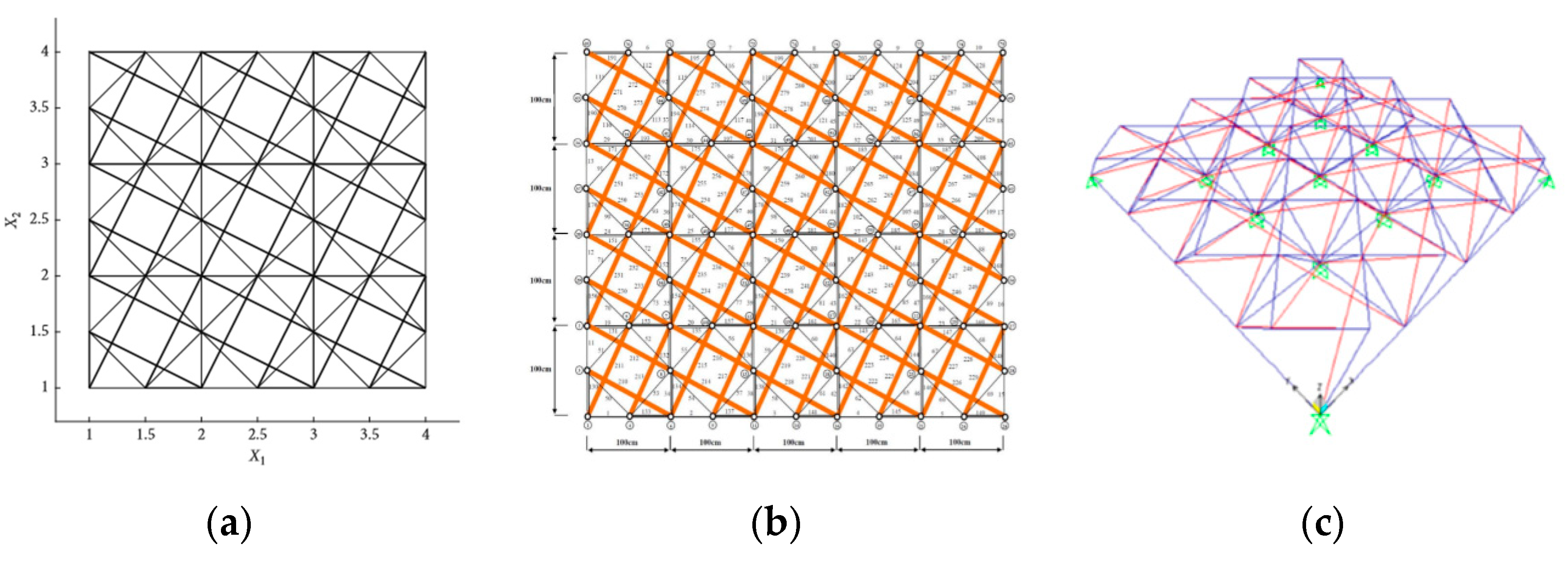
Figure 2.
Double-layered tensegrity grids built with modified Quartex: (a) model of Wang and Xu [22], (b) model of Faroughi and Lee [23], (c) model of the Sulaiman et al. [24].

Figure 3.
Double-layered tensegrity grids proposed by Al Sabouni-Zawadzka and Gilewski: (a) model from [39], (b) model from [41].

Figure 4.
Practical applications of tensegrity in civil engineering: (a) Blur Building [46], (b) a patio roof of a bank annex (Athens, Greece) [47], (c) an exhibition pavilion for Patras Cultural Capital of Europe (Patras, Greece) [47].

Figure 5.
(a) Space truss finite element, (b) global degrees of freedom of element .

Figure 6.
Geometry of the single modified Quartex module.

Figure 7.
Normalised self-stress state of the single modified Quartex module.

Figure 8.
Infinitesimal mechanism of the single modified Quartex module.

Figure 9.
Four-module tensegrity plate-like structure: (a) geometry, (b) models—bottom means that lower nodes 1–4 and 6–9 are supported; top means that upper nodes 10–12, 14–16 and 18–21 are supported.
Figure 9.
Four-module tensegrity plate-like structure: (a) geometry, (b) models—bottom means that lower nodes 1–4 and 6–9 are supported; top means that upper nodes 10–12, 14–16 and 18–21 are supported.

Figure 10.
Sixteen-module tensegrity plate-like structure: (a) top view, (b) models.

Figure 11.
Sixty-four-module tensegrity plate-like structure: (a) geometry, (b) models.

Figure 12.
Models of the tensegrity plate strips.


Table 1.
Tensegrity classification, based on [70].
Table 1.
Tensegrity classification, based on [70].
| T | S | C | M | I | D | |
|---|---|---|---|---|---|---|
| ideal tensegrity | + | + | + | + | + | + |
| “pure” tensegrity | + | + | + | + | + | – |
| structures with tensegrity features of class 1 | + | + | + | + | – | – |
| structures with tensegrity features of class 2 | + | + | + | – | + | – |
| – | + |
Table 2.
Coordinates of the nodes of the single modified Quartex module.
| No. of Node | x | y | z |
|---|---|---|---|
| 1 | a | 0 | 0 |
| 2 | 0 | 0.5a | a |
| 3 | a | a | 0 |
| 4 | 0.5a | 0 | a |
| 5 | 0 | a | 0 |
| 6 | a | 0.5a | a |
| 7 | 0 | 0 | 0 |
| 8 | 0.5a | a | a |
Table 3.
Numbers of elements of the single modified Quartex module.
| No. of Element | No. of First Node | No. of Second Node | |
|---|---|---|---|
| struts | 1 | 1 | 2 |
| 2 | 3 | 4 | |
| 3 | 5 | 6 | |
| 4 | 7 | 8 | |
| bottom cables | 5 | 1 | 3 |
| 6 | 1 | 7 | |
| 7 | 5 | 7 | |
| 8 | 3 | 5 | |
| middle cables | 9 | 3 | 6 |
| 10 | 1 | 4 | |
| 11 | 5 | 8 | |
| 12 | 2 | 7 | |
| upper cables | 13 | 2 | 8 |
| 14 | 2 | 4 | |
| 15 | 4 | 6 | |
| 16 | 6 | 8 |
Table 4.
Results of the qualitative analysis of the structures built with the modified Quartex modules.
Table 4.
Results of the qualitative analysis of the structures built with the modified Quartex modules.
| No. of Single Modules | Model | No. of Nodes (w) | No. of Elements (n) | Degrees of Freedom (m) | No. of Mechanisms | No. of Self-Stress States | Classification |
|---|---|---|---|---|---|---|---|
| 1 | SM | 8 | 16 | 16 | 1 | 1 | ideal tensegrity |
| 4 | P4-1 | 21 | 56 | 39 | 1 | 18 | structures with tensegrity features of class 1 |
| P4-2 | 45 | 2 | 13 | ||||
| P4-3 | 45 | 3 | 14 | ||||
| P4-4, P4-5 | 48 | 2 | 10 | ||||
| P4-6, P4-7 | 39 | 0 | 17 | structures with tensegrity features of class 2 | |||
| P4-8, P4-9 | 38 | 0 | 18 | ||||
| P4-10 | 39 | 0 | 17 | ||||
| 16 | P16-1 | 69 | 212 | 153 | 1 | 60 | structures with tensegrity features of class 1 |
| P16-2 | 156 | 0 | 56 | structures with tensegrity features of class 2 | |||
| P16-2 | 105 | 0 | 107 | ||||
| P16-3 | 129 | 0 | 83 | ||||
| P16-4 | 122 | 0 | 90 | ||||
| P16-6 | 146 | 1 | 67 | structures with tensegrity features of class 1 | |||
| 64 | P64-1 | 225 | 800 | 579 | 1 | 222 | structures with tensegrity features of class 1 |
| P64-2, P64-3 | 621 | 1 | 180 | ||||
| 4 | PS-1 | 21 | 56 | 39 | 1 | 18 | structures with tensegrity features of class 1 |
| PS-2 | 40 | 0 | 16 | structures with tensegrity features of class 2 | |||
| PS-3 | 27 | 0 | 29 | ||||
| PS-4 | 33 | 0 | 23 | ||||
| PS-5 | 32 | 0 | 24 |
© 2020 by the authors. Licensee MDPI, Basel, Switzerland. This article is an open access article distributed under the terms and conditions of the Creative Commons Attribution (CC BY) license (http://creativecommons.org/licenses/by/4.0/).
Share and Cite
MDPI and ACS Style
Obara, P.; Tomasik, J. Parametric Analysis of Tensegrity Plate-Like Structures: Part 1—Qualitative Analysis. Appl. Sci. 2020, 10, 7042. https://doi.org/10.3390/app10207042
AMA Style
Obara P, Tomasik J. Parametric Analysis of Tensegrity Plate-Like Structures: Part 1—Qualitative Analysis. Applied Sciences. 2020; 10(20):7042. https://doi.org/10.3390/app10207042
Chicago/Turabian StyleObara, Paulina, and Justyna Tomasik. 2020. "Parametric Analysis of Tensegrity Plate-Like Structures: Part 1—Qualitative Analysis" Applied Sciences 10, no. 20: 7042. https://doi.org/10.3390/app10207042
Note that from the first issue of 2016, this journal uses article numbers instead of page numbers. See further details here.